Today’s optics industry demands this level of optimal performance and precision. Read our feature in Laser Focus World to see how you can use SCI to your advantage.
Guernsey Coating Labs, a Ventura, CA-based company has supplied optical thin film coatings to the industry for over 40 years. Guernsey recently purchased a Zygo interferometer with an Äpre software upgrade. Ty Guernsey, President and Founder, shares how this has assisted in expanding capabilities for her company.
What challenges led you to invest in interferometry?
The interferometer lets us control the whole process reducing our customer’s risk.
Guernsey Coating Laboratories is an optical coating house with the mission to support our client’s needs. Working with our clients, we can now provide substrates on their behalf. A complete product (substrate plus coating) has been beneficial for many clients since it saves them extra time and steps in having to buy glass separately.
In the past, it was up to the client to take the responsibility for surface flatness. With our Varian spectrophotometer, Zygo interferometer, with Äpre’s 1MP camera, computer, and software upgrade, our clients can have more data regarding their product with precision information even before the finished optic is delivered.
The interferometer lets us measure the flatness of the substrate prior to and after coating. This helps during the inspection process in order to reduce our customer’s risk.
We can now determine whether the substrate is up to the flatness standards required pre-coating as well as the surface figure properties after coating is applied.
Surface quality of the substrate (as in under-polishing, scratches, digs) is imperative prior to production. However, it is also known within the industry that flaws are enhanced after coatings are applied. Using the interferometer will only determine the flatness.
Why did you choose Äpre?
Äpre’s open communication made the purchase straightforward.
Äpre was able to install software quickly, efficiently, and within a price point that made sense. Äpre also made the logical experience a breeze.
Did you look at alternative optical metrology solutions?
This interferometer and software upgrade was a great fit for our needs, driven by our customer requirements.
”Watching Guernsey Coatings’ success is so rewarding. Their interferometry system and software aren’t just another tool – it’s a way they live out their company mission by adding more value.” Robert Smythe, President, Äpre
What were installation and training like?
Äpre made the software installation easy and uncomplicated.
Although using the software was more of a learning curve, it was definitely not extensive. We’re very fortunate to have expert employees, some of whom have been with us for decades. They are cross-trained on our upgraded equipment making sure we keep projects going even when someone is on vacation.
What’s next for you and Guernsey?
With Äpre’s open communications and great rapport, we’ll continue to work together. I’ve been extremely happy at every point along the way.
It has been beneficial for us as well as our clients to have the interferometer added to our capabilities. When a client requires Guernsey to supply a substrate, we can now check the flatness of the glass, taking that responsibility off of the client. Any instrument that assists in providing an improved product is vital to the success of our client.
The field of thin film deposition is not without its’ challenges. Communication and transparency between ourselves as well as our clients is a foundation we strive to keep.
At ÄPRE we’re keeping our eyes on the horizon to boost your capabilities and profitability. Let us provide you with state-of-the-art systems to advance your process. Contact us today to get started.
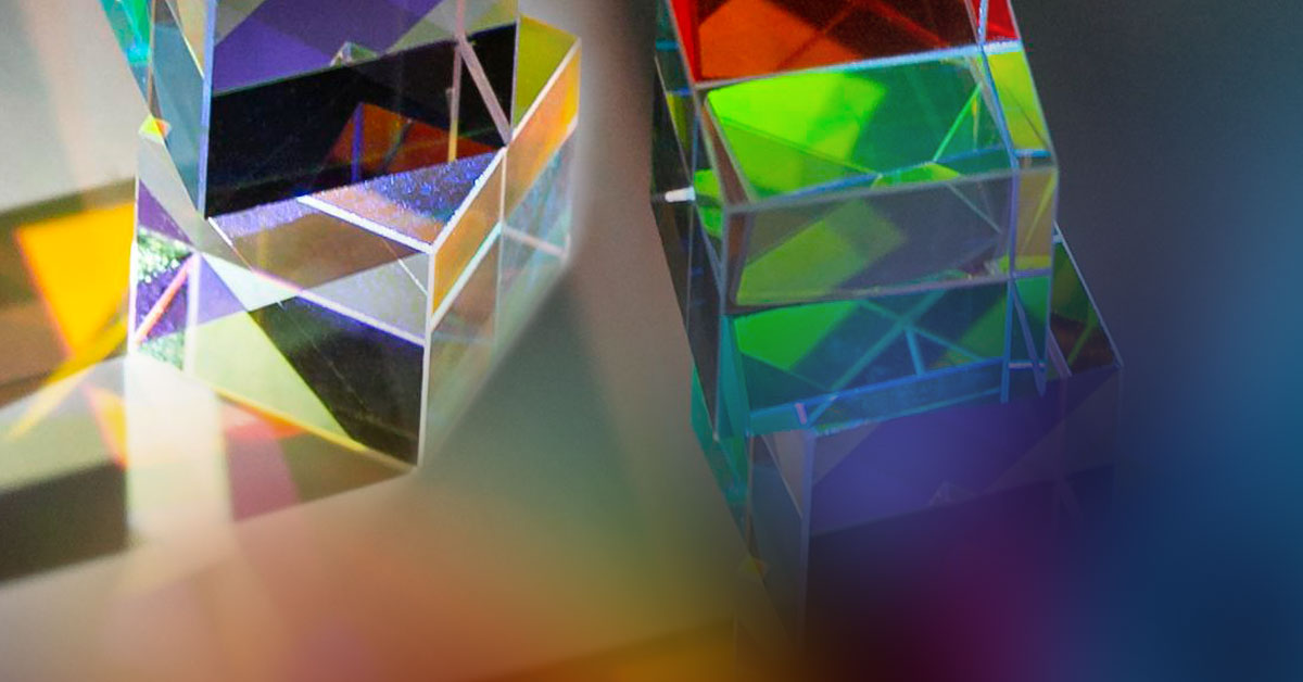
Prism stacks are difficult or even impossible to measure with a laser interferometer, yet are easy to measure with Spectrally Controlled Interferometry (SCI).
Examples of prism stacks for projector imaging systems, displacement measuring, monolithic or assembled component interferometers, and RGB combiners.
Laser Interferometer Back Reflections
A laser light source interferometers (for example a laser Fizeau) create fringes from every back reflecting surface. In some prism assemblies these are created in multiple channels and are superimposed creating confused interference patterns that are impossible to measurement.
Spectrally Controlled Interferometry Eliminates Back Reflection
Spectrally Controlled Interferometry (SCI) can selectively isolate the interference cavity of interest for easy and accurate measurement. And as opposed to white light “delay line” interferometers, SCI is easy to align alignment prior to measurement using its long coherence alignment mode.
Imaging System Prism Stack
In an imaging prism stack the transmitted wavefront passes through several back reflecting surfaces, see figure 1. In this case there are four potential back reflection surfaces. SCI can measure each of these independently if the surface is of interest, or only the transmitted wavefront without corruption. This allows a straight on measurement without tilting or distorting the wavefront.
Figure 1: Schmidt-Pechan Prism. The circled interfaces are areas where back reflections can prevent accurate measurements with a laser interferometer. (ref. https://commons.wikimedia.org/wiki/File:Schmidt-Pechan_prism.svg)
Displacement Measuring Interferometer Components
Interferometers for displacement measurement typically have multiple channels for the test and reference beam path. SCI enables the measurement of each channel independently, without the degrading influence of multiple entry and exit surfaces. To select the measurement channel cavity the polarization is rotated by 90º from one to the other, which is accomplished at the interferometer. [A linear polarized interferometer, where the polarization can be rotated, is used for this application. Contact ÄPRE for more information.]
Figure 2: a-WOW Interferometer for measuring displacement and angle. (ref. Loughridge, Russell & Abramovitch, Daniel. (2013). A tutorial on laser interferometry for precision measurements. Proceedings of the American Control Conference. 3686-3703. 10.1109/ACC.2013.6580402.)
RGB Prism Combiners
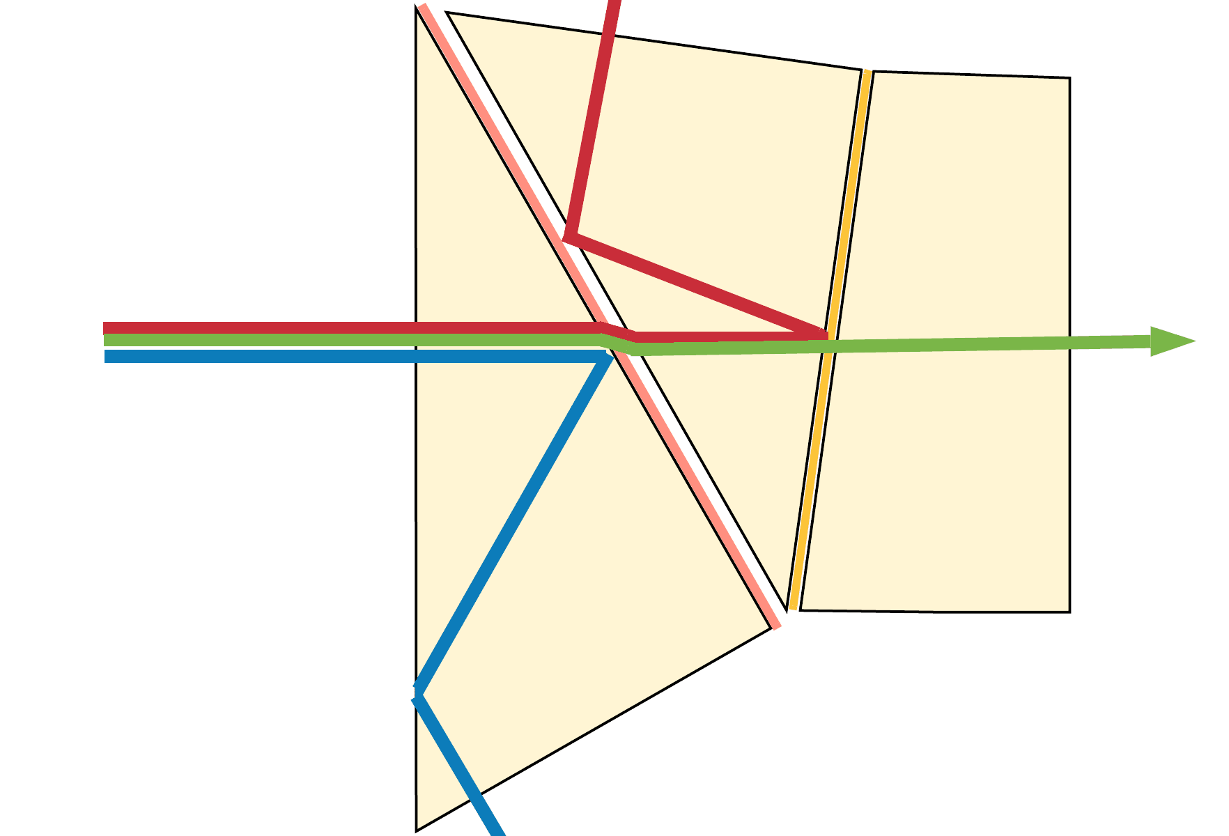
RGB (red-green-blue) prism combiners are particularly difficult to measure. The three channels must be separated to measure each path’s transmitted wavefront, yet optically they are co-axial. With a laser interferometer this is impossible, as all the wavefronts overlap, see figure 3. Plus there are multiple back reflecting surfaces that must be eliminated for an accurate measurement. Each channel can be aligned independently in the long coherence align mode. Then selected in the short coherence mode for accurate measurement.
Figure: 3: Dichroic Prism for RGB selection. The red circle indicate surfaces that reflect back into the interferometer confusing or suppressing the measurement.
Interferometer resolution
Many RGB prism combiners are classed as micro-optics with a less than 6 mm clear aperture. Therefore a standard 4 inch (100 mm), zoomed imaging interferometer with ~400µm image resolution or worse at all zoom magnifications, has insufficient image resolution. A minimum of 60 µm image resolution is required to measure the wavefront of a 6 mm clear aperture prism. 60 µm resolution yields a 100 X 100 image resolution across a 6 mm clear aperture.
Figure4: Image resolution demonstrated for 100 mm aperture interferometer. Airy disk size properly sampled at ≥Nyquist limit is required
NOTE: This is not 100 X 100 pixels but image resolution. The camera array must be 2X this or a minimum of 200 x 200 pixels AND the imaging optics must produce an airy disk size of 60 µm. At 100 X 100 image resolution 36 Zernike polynomials are accurately calculated. See Figure 4.
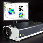
Shown in figure 5 is ÄPRE’s S6|HR interferometer with 15 µm image resolution capable of measuring the transmitted wavefront in components to 1.5 mm clear aperture.
Figure 4: ÄPRE S6|HR interferometer with SCI light source for measuring micro-optics including prisms and prism assemblies.
Spectrally Controlled Interferometry Separates the RGB Channels
Again with a laser interferometer the three channels create back reflections simultaneously making the measurement impossible. In the measurement set up (see figure 5) each six prism assembly cavity has three cavity of different optical path lengths. Therefore the distance between the test and reference flat is different for each channel. With SCI each channel is selected one-at-a-time. Typical measurement results with SCI and S6|HR are shown in Figure 6.
Figure 5: RGB Prism assembly setup with S6|HR Interferometer.Figure 6″ Typical results measuring an RGB prism assembly with S6|HR and SCI. One setup three results in seconds.
Summary
Prisms assemblies are difficult optical elements to measure. Back reflections from multiple surfaces and multiple channels make laser interferometry incapable of making these measurements. SCI offers an easy to use, accurate method to measure these components for the first time.
The laser Fizeau interferometer has experienced several transformations from its original design. Like all evolutionary processes, some vestigial design elements remain in commonly used interferometers, which do not address and can impede measurements required to control and optimize today’s optical manufacturing processes.
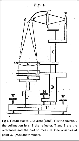
Circa 1850: Fizeau Interferometer
Armand Hippolyte Louis Fizeau (1819 – 1896) invented the interferometer configuration, now named after him, for measurements of glass parameters which he presented at the French Academy of Sciences in 1862. Earlier, in 1851 he used a version of this interferometer in his famous experiment devised to test the ether-drag theory. The results seemed to support a partial ether-drag, that were later confirmed by Michelson and Morley. In a twist of fate the ether theory was disproved shortly after by the more famous Michelson-Morley experiment, but the results of BOTH of these experiments lead the way to Einstein’s theory of relativity. “Einstein later pointed out the importance of the [Fizeau] experiment for special relativity, in which it corresponds to the relativistic velocity-addition formula when restricted to small velocities,” Wikipedia
Armand Hippolyte Louis Fizeau1st Fizeau Interferometer
Pre-1960’s
Before the invention of the laser in the 1960’s optical test interferometers were difficult to use and often had to be custom built for each application. Low-coherence illumination favored equal path interferometers like a Twyman-Green or Mach-Zehnder configuration. The Fizeau – though already commercially available – were large, very heavy, difficult to use and limited to measurements of flat surfaces.
The most popular interferometer, though rarely considered one, is the Test Plate using Newton’s Rings. A test plate is strikingly similar to a Fizeau configuration with only several micrometers of working distance. The test plate consists of one reference surface for each surface an a low coherence filtered source
Twyman-Green InterferometerTest Plate
1960’s – The Laser becomes Practical
The laser made interferometry much easier to implement. “Bob Hopkins…was quick to realize how much the laser could be used to improve the testing of optical components” (J.C. Wyant, “Short history of interferometric metrology”). With the laser, fringes were easy to find making interferometry a practical tool supporting optical manufacture. Much progress was made in testing configurations, yet interferometry remained an experts tool, custom made for the application and developed and run by engineers and scientists. Plus to use a HeNe laser, the most widely available required stabilizing it to have only one frequency of output. Low cost unstablized HeNe lasers had short coherence, around 200 mm and were limited to use in a Twyman Green configuration where the test and reference could be balance. These stabilized lasers were very expensive, in 2020 dollars they would cost $35,000!
The 1st HeNe Laser – Bell Labs (J. Hecht, “History of Gas Lasers, Part 1 Continuous Wave Gas Lasers”, Opt. Phot, January 2010)
1970’s – The Modern Fizeau Architecture is Created
What is now considered a Fizeau interferometer was created in the 1970’s by two different events: The invention of the modular Fizeau interferometer with a laser source, plus computerized phase measurements.
The Fizeau Optical/Mechanical Architecture
The HeNe laser promised to make interferometers much easier to use, but its cost blocked interferometers from becoming a commercial success. The key insight at Zygo that enabled the modern Fizeau interferometer design was that a simple polarizer in front of a multi-mode, low cost laser produced meters long coherence. This insight was applied in 1972 by Carl Zanoni and George Hunter at ZYGO constructing the GH (for George Hunter the principle designer) and the follow-on Mark II™ in 1976 when modern interferometry was born.
GH Interferometer: Transmission Sphere/Interferometer Architecture with Polaroid fringe captureMark II™ interferometer: Vidicon Tube Camera introduced for live fringe viewing
It is important to understand the architecture of the Mark II™ to know WHY interferometers are designed as they are today. The ZYGO innovations were a low cost, long coherence laser, a flexible optical architecture, a simple alignment system, with a clean fringe image. The architecture combines an interferometer (“mainframe” in ZYGO terminology in a nod to the 1970’s Tektronix Oscilloscope architecture) with quickly interchangeable reference lenses/reference-surfaces they named transmission spheres (TS) and transmission flats (TF).
With the long working distance due to long laser coherence one TS eliminated the need for large libraries of Test Plates – bringing cost savings and convenience. Plus Test Plates are used in virtual contact, separating the optical test surface from the reference surface eliminated the possibility of scratching and damage.
Ease of use was augmented by the alignment system. The twin spot alignment visually indicated when the cavity alignment was close enough for interference fringes to be found. Now non optical engineers could align and configure an interferometer.
The imaging system of Mark II™ REQUIRED a zoom lens to measure a wide range of part diameters since the only imager available was a vidicon camera. Both the zoom lens and the vidicon produced back reflections and secondary fringe patterns. The solution was a rotating ground glass, “coherence buster”, at an intermediate image that was then imaged incoherently through the zoom lens and onto the vidicon.
Zygo Mark II™ optical design architecture – from the patent drawing
Mark Interferometer Design Limitations
This design was so successful that even today’s interferometers with ground glass and 6X zoom are IDENTICAL to the optical system designed for the Mark II™. This is important to understand since the original optical system was designed for a vidicon camera AND only considered the visual measurement of spherical and flat optics manufactured with pitch polished processes.
If a megapixel camera is used in this design, the magnification by the zoom lens is empty, meaning resolution is not increased and potentially degraded. Further, imaging distortion of one or two pixels at 128X128 was acceptable but is problematic when spot polishing techniques are employed that require interferometer feedback for correction. These limitations lead to the development of fixed or stepped magnification imaging systems in the 2000’s, to be discussed later.
The historical influence of the Mark II™ optical architecture cannot be underestimated. All commercially successful interferometers follow the laser + “mainframe” + Transmission Reference architecture. Plus commercially successful alternative optical imaging design were only developed in the 2000’s, where even today (2018) historical inertia drives buying decisions.
The Data Acquisition System
Bell Labs patented computer data acquisition phase measuring interferometry. John Bruning and Donald Harriott’s group and Tropel (now CORNING) worked together to develop the a phase measuring system.
In the 1970’s Bell Labs was pushing the leading edge of semiconductor manufacturing technology. Lenses to support semiconductor manufacture were difficult to build due to their, at the time, extreme tolerances. Conventional visual or fringe center data analysis was not sufficient. Minicomputers were available and enabled in-the-lab data acquisition, as opposed to central batch processing of a few years earlier. Add to this signal processing was a core technology at Bell Labs. This combination enabled retrieving interferogram phase, pixel by pixel, an innovation that started the explosion of development that has continued until today.
Phase acquisition was achieved by changing the interference cavity length by λ/4, stopping, capturing a 32 X 32 sampled camera frame, moving another λ/4 step, frame grab…until four camera frames were captured. A simple calculation eliminates the background intensity term and isolates the phase for each pixel. This is commonly called Phase Stepping Interferometry. Phase Stepping was used to minimize errors due to phosphor hysteresis.
TROPEL (CORNING) developed the first commercial computerized Phase Stepping systems. These were vertical laser interferometers that operated in the Twyman-Green and Fizeau mode. Data processing included a 32X32 array data acquisition off a vidicon tube camera.
A few years later Jim Wyant at WYKO introduced Phase Shifting, where a phase was continuously swept and not stepped, improving accuracy and measurement speed. This method was enabled by the use of CCD sensors.
1980’s – The Digital Age
Developments in the 1980’s centered upon improving data acquisition. In-fact data acquisition was the locus of improvements over the next 20 years. ZYGO became the dominant provider of interferometers with TROPEL deciding to concentrate on in-house development supporting ultra-high accuracy metrology and application focused systems (to be discussed later).
Digital Cameras
Digital cameras were now commercially available. The ZYGO Mark III™ had a 100 X 100 pixel array CCD and a home built board level computer with a frame grabber, with data acquired using a 4 frame data acquisition algorithm.
Vidicon Tube and CCD Imager
Software and Computers Enhance Performance
The second half of the 1980’s saw the development of the ZYGO Mark IV™ with a “high-density processor” system with a 256×256 array CID camera. The Mark IV HDP system was based on ZYGO’s own computer, computer operating system and internally developed Basic-like software language that was then scripted into a user interface. The software package allowed for custom scripting which required intensive software support. The software was slow and expensive to develop, difficult to use and quickly out of date.
Zygo® MarkVI Software User Interface
In the 1980’s Wyko Corporation emerged to commercialize the phase shifting microscope and then the Fizeau interferometer. WYKO was innovative regarding data acquisition and software. Based on commercially available computers, operating systems and development software, innovative uses of cameras and phase modulators, WYKO data acquisition systems evolved more quickly than ZYGO.
WYKO’s Innovation enabled the industry to quickly see the value of software to present easy to understand data and also employ algorithms to improve the quality and speed of data analysis.
Wyko 6000 Laser Fizeau Interferometer and software
These innovations include color plots, extended analysis in MTF, PSF, and Fourier based analysis that pushed the industry forward.
This competitive pressure drove ZYGO to develop MetroPro™ the program which became the industry standard software for the next 25 years. MetroPro™ was based on Objective-C an early and quickly obsolete programming language. Yet using the object oriented software gave MetroPro™ the flexibility to survive all those years.
The competition between WYKO® and ZYGO® benefited the optics community tremendously as they challenged each other to improve.
MetroPro™ Software
Innovation in the 1980’s
Wavelength Modulated PSI
Phase shifting data acquisition require the phase of the cavity to change. Changing the cavity OPL can be accomplish by slightly changing the wavelength [Gary Sommargren], its commercial application was not fully implemented until 15 years later. (Note: cavity phase can also be modulated via phase modulating the source spectrum, see SCI in the 2000’s)
Vibration Insensitive Interferometry
Two significant inventions that would not become commercially successful until the 2000’s were invented in the 1980’s: Carrier fringe [Takeda, H. Ina and S. Kobayashi] and multi-camera frame simultaneous interferometry [Smythe & Moore]. Both of these enable phase measurement at microsecond rates enabling interferometry in vibrating and turbulent environments.
1990’s – Software and Computers Improve Performance
The Personal Computer revolution of the 1990’s and continuous improvements in semiconductor imaging (CCD’s) were the basis of most improvements in the 1990’s. The Mark II architecture was maintained and repackaged, while faster computers, improving software analysis and higher density cameras were added.
Algorithms
A new concentration on algorithms occurred. It was seen that a robust algorithm could compensate for errors in the data acquisition and environment. New multi-frame algorithms [Creath, Degroot] were created throughout this period.
In tangential fields of speckle interferometry, vibration correction algorithms were being developed that would find their way into Fizeau interferometry after 2000. These so called Vibration Tolerant PSI algorithms make Fizeau Interferometry more accurate in environments where data can be obtained but ripple appears in the data.
High Volume Manufacturing
The growth of high volume manufacture in Asia led to new entrants. The relative expense of WYKO and ZYGO systems positioned them in the market as the R&D and QC standards for wavefront measurement and Fujinon and Olympus emerged as the small aperture interferometers providers for surface and wavefront production measurement.
Molded optics, pioneered at KODAK in the USA in the early 1980’s, led to new consumer cameras and optical data storage devices driving the need for high volume asphere metrology. Interferometers were not able to measure these lenses or molds, leading to rise of stylus profilers from Taylor Hobson and Panasonic. It was not until the early 2000’s that interferometers were developed to measure aspheres.
In the early 1990’s Dr. Michael Küchel, of Carl Zeiss, developed the Direct 100 laser Fizeau, a multi-wavelength optical interferometer with advanced optical architecture and data acquisition based on carrier fringe. Custom electronics acquired data at frame rates. The Direct 100 architecture is still employed today in some non-commercial applications. Phase Shift Technology also introduced a multi-camera interferometer on a custom basis. The expense of these interferometers limited their commercial success.
New Source Modality Discovered
A “White Light Fizeau Interferometer” was created by Professor Schwider in 1997. The light source was a broadband source with spectral content. The unique result was interference fringes a fixed distance from the Fizeau reference surface.
Modern History
It is difficult to determine what are the “landmark” developments without the passage of time. For the last 18 years we will simply review some of the major technology and products introduced to solve a greater range of application via Fizeau interferometry
2000’s – Data Acquisition, Imaging, Illumination, Aspheres and Workstations
Deterministic optical manufacturing drove innovation in the interferometry market. The dominant manufacturing technique up to the 2000’s was pitch polished spheres and flats, which the old Mark II™ could handle. Now, new spot polishing computer controlled machines rendered the capabilities of old style interferometers insufficient. In order to keep pace with the advances in optical manufacturing, optical polishing production had to be capable of the following:
Minimizing image distortion for accurate positioning
Calibrating image size in order to know artifact position
Contain a high resolution optical system in order to detect the mid-spatial frequencies
The ability to produce sharp images all the way to the edge of the image in order to minimize coherent artifacts at the object’s edge
Measure very steep surfaces approaching hemispheres
CNC Polishing Drove the Need for Improved Fizeau Interferometers
Imaging Improvements
In order to accommodate the industry’s new demands, the Mark II type instruments had to be abandoned. Interferometers with fixed magnification and low distortion imaging, calibrated image size and high pixel resolution emerged.
Workstations
Integrated workstations were developed primarily in Germany in order to move interferometers out of the quality control laboratory and next to the polishing equipment. The advantage of a workstation was the efficiency of integrating an interferometer directly into the production process to measure both surface form and radius of curvature easily and occupy as little floor space as possible.
Commercial laser Fizeau workstation
Data Acquisition
Vibration Insensitive Commercially Viable
4D Technology introduced a Simultaneous Phase Measuring Interferometer (SPMI) that was the first commercially successful interferometer of its kind. By combining the TROPEL 4-camera approach onto a single detector, the system became robust and easy to use [Novak et. al.]. The expanded manufacture of large mirrors for space and terrestrial application gave 4D Technology an application to establish their business and become a major player in the interferometry market.
4D Data Acquisition System: 1 Camera with 4 Phases
A different approach to eliminating vibration sensitivity was developed by ESDI [Szwaykowski et.al.], which introduced the concept of a spatially split source using a high coherency laser in a Fizeau interferometer. This allowed for the simultaneous capture of 3 phase-shifted interferograms.
Carrier Fringe data acquisition also became common as simple PC computers became fast enough to acquire and analyze data sets.
Scanning Fizeau Asphere
An asphere measuring interferometer was introduced by ZYGO. This was a scanning Fizeau [Küchel] that built up rings of data as the part scanned along its optical axis to measure each asphere zone. The zones were then combined to map the as much of the surface as could be accessed.
Scanning Fizeau Interferometer for Asphere Measurement
Stitching of Fast Convex Spheres & Aspheres
QED introduced a practical stitching system [Forbes et.al.] to measure steep, approaching hemispherical spheres. Beside more coverage of steep spheres, higher accuracy due to averaging and potentially higher spatial frequencies were being reported.
Light Source
Several modifications to the point source were introduced in the late 1990’s/early 2000’s which attempted to reduce diffraction artifacts caused by dust particles and other imperfections in the optical system of the interferometer. These were based mostly on increasing the size of the source by projecting a pattern using highly coherent light from the laser onto a rotating ground glass. Such sources with a decreased degree of spatial coherency can eliminate coherent patterns produced by diffraction on small particles and can be very effective, especially when such particles are located far away from the imaging plane.
In order to handle measurements of optical components with parallel front and back surfaces, ZYGO introduced a tunable, coherent laser source [Deck] in which the wavelength of light can be swept in a controllable way. This innovation enabled analysis based on a Fourier transformation. Additionally, separate reflections from the front and back surfaces of the sample could be taken in one measurement, which allowed for independent measurements of those surfaces. This method also made it possible to take measurements of the sample optical thickness. This technique is limited to ~1.5 mm optical thickness, limited by the scanning range of lasers. Also the thinner the part the longer the measurement time, up to 60 seconds, making the acquisition vulnerable to environmental vibrations and air turbulence decreasing repeatability of measurements.
Vibration Insensitive/Low Coherence
4D technology introduced a system to solve the long-standing problem of errors caused by vibrations in the machine and testing environment while minimizing coherent artifacts. They used a delay line and a synchronous translation of two components: the reference element and one of the mirrors in the delay line to achieve the vibration-insensitive performance in their model of the Fizeau interferometer. The drawback of such an approach was that it led to complicated architectural design.
Ring Source/Partial Coherence
ZYGO introduced the ring illumination system [ Küchel]. It is similar to a method used by Zeiss [Küchel] in their high performance interferometers. The ring increasingly lowers image artifacts contributions to the measurement the FARTHER the artifact is from image plane. So dust near the launch of the illumination beam is more suppressed than in the reference element. At catseye the ring must be reduced to a spot or no interference is observed due to the wavefront flipping. Similar approaches with a simple enlarged dot illumination are also utilized over shorter optical cavities. The dot could be considered temporally coherent and spatially incoherent.
2010’s – High Resolution Imaging, Low Retrace Errors and Spectral Source
CNC polishing machines require rapid and precise feedback between measurement results and fabrication processes. Ideally, an interferometer should be used in a closed loop as a guiding tool in the polishing operation; these needs drive the requirement for low retrace errors, low image distortion, high spatial resolution and acceptance of large departures from “null” condition.
New Interferometer Designs
The older systems, with Mark II™ legacy 6X zoom optics and intermediate fringe images projected on rotating ground glass disks, are inadequate to support CNC polishing applications. In response, 4D Technology and later ZYGO introduced high pixel count interferometers with better image resolution. These systems have better imaging and higher slope acceptance.
Äpre Instruments took interferometer design a step further with balanced optical designs. The HR interferometers for computer controlled polishing applications and the SR interferometers for General Purpose optical shop testing,
HR-High Resolution
ÄPRE S-Series HR interferometers for computer controlled polishing applications or where the highest image resolution and wavefront slopes are required.
Diffraction limited 2K X 2K spatial resolution (not just pixel count)
<0.1% image distortion
<λ/20 retrace errors at 500 fringes of tilt
Up to 650 fringes of slope across the aperture
SR – Standard Resolution
ÄPRE S-Series SR interferometers are for general purpose optical ship testing. The SR finally replaces the 40-year-old Mark II optical design; outperforming the old design by large measure, without increasing the price to the user.
Diffraction limited 1K x 1K spatial resolution (not just pixel count)
<0.1% image distortion
<λ/20 retrace errors at 250 fringes of tilt
Up to 375 fringes of slope across the aperture
Surface of Interest Isolation
Spectrally Controlled Interferometry (SCI™)
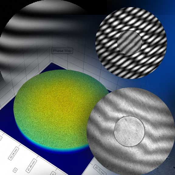
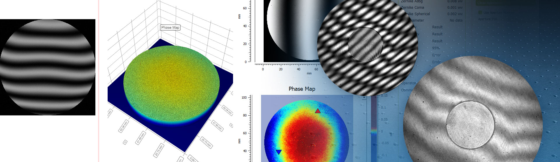
ÄPRE has introduced a practical SCI source [Olszak], a new source modality to Fizeau interferometry. SCI controls the coherence, fringe position (over 100’s of millimeters) and phase modulation of the fringes electronically. SCI aligns in high coherence mode, like a laser, isolates like a white light source, positions the fringes within the cavity, and phase modulates regardless the cavity size, even down to 50um. By isolating the surface of interest, accuracy is improved and new applications are enabled. This is a new technology and its impact will emerge in the coming years.
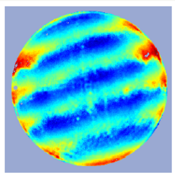
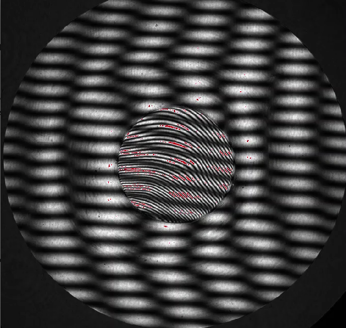
Laser Fizeau compared to SCI Fizeau – 1 cm substate with 250 um step in the middle.
Delay Line Surface Isolation
4D Technologies introduced a light source based on a coupled delay-line to project low coherence fringes. Working in a plano-cavity it can place low coherence fringes a distance from the TF and move them over ~25 mm range. Isolating the surface of interest.
Appendix – Hidden Developments
Throughout the history there have been groups developing interferometers whose performance was never made public due to proprietary or classified project constraints, e.g. Perkin Elmer, ITEK, Zeiss, Nikon, Canon, Tropel, etc. Some of these systems were more advanced than available commercial systems, or even disclosed technology in open publications of the time.
Unfortunately these pioneers are not recognized in the open literature, but they too have significantly advanced the state-of-the-art of interferometry and optical manufacturing.
Fizeau Interferometer to Measure Precision Aspheres
Summary
The Fizeau interferometer has a long history and promising future. Interferometers will continue to evolve as applications and processes drive the need for change and new technologies enable these changes to be implemented.
Contact ÄPRE to discuss your interferometery needs to apply the best source + interferometer to your application.
Note: We welcome your comments or additions to make this history more complete.
Jan Posthumas of LaserPeak (on left) and Don Pearson, ÄPRE’s VP Sales (on right)
Don Pearson, our VP Sales and Jan Posthumas, of LaserPeak (ÄPRE Representative) presented ÄPRE’s S100|HR interferometer in Munich this June. Once again we were pleased to meet with, and make new friends while co-exhibiting with the PTB’s HLEM (Hi-Level Experts Meeting) group.
Presented was the S100|HR, part of ÄPRE’s S-Series interferometers with diffraction limited imaging to 50 µm resolution (S50|HR), and all with <0.1% image distortion and <λ/20 retrace errors even at 6.5 fringes/mm.
We were also pleased with the interest in our new SCI based system that electronically remove back reflections from measurements and we look forward to discussing this more in the future.
Rarely are errors due to the interferometer itself considered when measuring optics with a laser Fizeau interferometer. Piotr gives examples of common and significant errors generated in the interferometer. Click to download his presentation with notes here.
The new S100|HR laser Fizeau interferometer was introduced at the Optatec tradeshow in Frankfurt Germany this past week. We are excited by the industry’s response to a high-performance system offered at a fair price, and the continued interest in interferometer upgrades. The S100|HR was displayed measuring in the vibration insensitive mode and performed flawlessly.
This year we co-exhibited with the PTB working group for precision optical metrology. Thank you to Heiko and his team for coordinating the booth set up and the great catering! Everyone was very supportive.
OptoTech GmbH displayed our S100|HR integrated into their new OWI 150 Inverse workstation. This high performance workstation measures radius of curvature over 1 meter and surface figure while using ÄPRE’s REVEAL software in an OEM configuration. This is a great example of the power of REVEAL to automatically read the Z position to measure radius of curvature and to be modified to a specific customers requirement. OptoTech favors a more classic appearance including a dark blue background to be more familiar to users.
Again thank you to all who visited us at Optatec this year.
Our next show is Optics and Photonics in San Diego California. See you there!
This blog post discusses improvements in phase shifting algorithms for increased accuracy.
From the earliest days of phase shifting interferometry (PSI) phase ripple has been a problem. Ripple in the phase data follows the live fringe pattern but with twice the fringe frequency (ripple with the same frequency as the fringes can also appear and will be discuss at the end of the article). Ripple is an increase in measurement uncertainty (lower accuracy) and thus needs to be minimized. Further ripple can mimic mid-spatial frequency errors confusing the control feedback when spot polishing. Thus its minimization is important to good quality control.
Correcting Phase Ripple
In the late 1970’s Phase Ripple was called the “ripple bug” and its origin was unknown. The primary source was found to be vibration in the interferometer cavity during the data acquisition, and later other sources were identified such as nonlinearities in cameras and the phase shifting mechanisms. Any deviation from equally spaced phase shifts during acquisition or non-linearities that distorted the shape of the fringes cause ripple to form. Cameras became more linear with the advent of the then new CCD’s, and control of phase shifting mechanics improved, yet vibration is always present.
Nulling the Fizeau Cavity to Minimize
The first technique to minimize ripple was simply to null the cavity. By minimizing the visible fringes, the ripple is spread across the data. If perfectly nulled the ripple is insignificant when the test surface is a perfect sphere. This is still good practice as a nulled cavity exhibits the least errors in a Fizeau interferometer. Yet it is not always possible to null the fringes and so ultimately a better approach was needed.
Improved Phase Shifting Algorithms
In the early 1980’s the standard phase algorithm was four camera frames (buckets) spaced by 90°. Jim Wyant pointed out that only three frames were required to find phase, but this algorithm is particularly vibration sensitive. Four frame PSI, initiated by John Bruning’s group1, was less sensitive and in the late 1980’s Hariharan2 introduced a five frame PSI algorithm that was better than both. In 1988 Kathy Creath3 investigated numerous algorithms with varying sensitivity to ripple and in 1997 Peter Degroot4 wrote a “definitive” paper on phase shifting algorithms. These approaches made PSI less sensitive to phase shift spacing and the jitter between phase frames, but did not directly address the unequally spaced fringes due to vibration.
New Approach: Post Acquisition Correction
Ripple in Phase Data and Corrected with Äpre Universal Phase Algorithm
In 1982 Morgan5 investigated applying a post acquisition least squares correction to PSI. In the 1990’s a parallel line of investigation became active. This approach corrects the acquired data to the expected phase shifts through mathematical optimization. I.Kong and S. Kim 6,7 created a least squares PSI algorithm and an algorithm to “automatically suppress phase shift errors”, followed by C.Wei, M. Chen, & Z. Wang 8 with a “General Algorithm for phase-shifting interferometry by iterative least squares fitting”. Over the next 10 years a flurry of work 9,10,11,12,13,14,15 developed algorithms immune to translational and in some cases tilt shift error using iterative optimization. These works established the methodologies for vibration tolerant algorithms and demonstrated that with fast computers phase shifting errors could be minimized algorithmically, and practically.
Commercially Available Today
Vibration tolerant PSI, based on 35 years of development, are now commercially available as found in ÄPRE’s “Universal Phase Algorithm”6 in REVEAL™. The universal phase algorithm effectively minimizes phase ripple, as long as the vibration does not exceed ~150 nm P-V (λ/2 fringe). If the vibration exceeds 150 nm P-V then phase shifting interferometry breaks down and simultaneous PSI (Multi-Camera or Carrier Fringe) is required.
Vibration is not the only source of phase ripple
Intensity Variations
When phase ripple appears at the same frequency as the fringes illumination intensity variation during measurement is a likely cause. This can occur due to a laser or light level control failing. Interestingly, in interferometers equipped with rotating diffusers, variations in light level may occur due to differences of transmissivity in different areas of the diffuser rotating disk or simply by dirt on the diffuser disk.
Fringe Contrast Variations
Fringe contrast (modulation) is generally defined by the coherency of the source and is usually quite stable. However a laser can exhibit variations when the source is not properly stabilized. Also laser instability can be caused by mechanical vibrations when combined with long exposure times (usually longer then 10 ms.). In the later case the moving fringes will “average out” over a small area causing a loss of modulation that may be different for each recorded fringe image. The combination will create phase ripple in the data.
Tilt Variations
Vibration is considered a “piston” term – equal for every pixel across the aperture. If the phase shifting mechanics do not move straight the phase shifts will vary across the aperture, causing uncorrected ripple even with a correction algorithm. Recent work9,14 has attempted to address this error. This tilt induced ripple can also occur if the test or reference is not rigidly mounted.
Test or Reference with High Reflectivity
When one of the test parts has a high reflectivity fringes are detected that have reflected several times within the cavity. These multiple reflections distort the fringe shape. PSI algorithms, including vibration tolerant algorithms expect sinusoidal fringes. The distorted fringes are non-sinusoidal and induce phase ripple. To suppress the multiple reflections special coatings are applied to the reference or a thin pellicle is placed between the test and reference to suppress the multiple reflections.
References:
J. H. Bruning, D. R. Herriott, J. E. Gallagher, D. P. Rosenfeld, A. D. White, and D. J. Brangaccio, “Digital Wavefront Measuring Interferometer for Testing Optical Surfaces and Lenses”, Appl. Opt. 13, 11, 2693-2703 (1974)
P. Hariharan, B. F. Oreb, and T. Eiju, “Digital phase-shifting interferometry: a simple error-compensating phase calculation algorithm”, Appl. Opt. 26, 13 2504 – 2506 (1987)
K. Creath, “Phase-shifting interferometry techniques,” Progress in Optics, E. Wolf, ed. (Elsevier, 1988), Vol. 26, 349-393
C.J.Morgan, “Least-squares estimation in phase-measurement interferometry”, Opt. Lett. 7, 368-370 (1982)
I.B.Kong & S.W.Kim, “General Algorithm for phase-shifting interferometry by iterative least squares fitting”, Opt. Eng. 34, 183-187 (1995)
I.B.Kong & S.W.Kim, “Portable inspection of precision surface by phase-shifting interferometry with automatic suppression of phase shift errors”, Opt. Eng. 34, 1400-1404 (1995)
C.Wei, M. Chen, & Z. Wang, “General phase-stepping algorithm with automatic calibration of phase steps,” Opt. Eng. 38, 1357-1360 (1999)
Chen, Guo and Wei, “Algorithm immune to tilt phase-shift error for phase-shifting interferometers”, Appl. Opt, 39, 22, 3894 – 3898 (2000)
K.G.Larkin & B.F.Oreb, “Design and assessment of symmetrical phase-shifting algorithms”, J. Opt.Soc.AM. A 9, 1740-1748 (1992)
K.G.Larkin, “A self-calibrating phase-shifting algorithm based on natural demodulation of two-dimensional fringe patterns”, Opt. Expr.9, 236-253 (2001)
H.Guo & Z.Zhang, “Phase shift estimation from variances of fringe pattern differences”, Appl. Opt. 52, 26, 65726578 (2013)
Y-C Chen, P-C Lin, C-M Lee, & C-W Liang, “Iterative phase-shifting algorithm immune to random phase shifts and tilt”, Appl. Opt. 52, 14, 3381-3386 (2013)
M.Wielgus, Z. Sunderland, K. Patorski “Two-frame tilt-shift error estimation and phase demodulation algorithm”, Opt. Letters 40, 3460-3463, August 1 2015
L. Deck, “Model-based phase shifting interferometry”, Appl. Opt. 53, 4628-4636, July 2014
P. Szwaykowski, “Minimization of vibration induced errors using a geometrical approach to phase shifting interferometry”, ASPE Summer Conference on Interferometry, July 2015
This blog is about the performance and price options for laser Fizeau interferometers
Up to this point we have been discussing how various applications require specific interferometer sensor configurations and features. Now comes the key point when you need to do something. Do you need increased production capacity? Has a new process been introduced that requires better feedback? Is the IT department concerned about an old operating system? Has the computer failed, or the system has become unreliable but meets your production needs? Do you have a new program that requires a dedicated system? Or your customer is pushing for a result your system does not produce. What do you do? Do you buy a new interferometer? What are the options?
Buy New, Upgrade or Buy Refurbished?
Asking some questions can lead you to the purchasing options to consider.
Is the system to support a spot polishing process where slopes and mid-spatial frequencies are important?
Yes – indicates a high performance imaging interferometer with a 2K X 2K level camera, low distortion and low ray-trace errors.
Is the environment harsh, with vibration and air turbulence present?
Yes – indicates a SPMI (Multi-detector or Carrier Fringe acquisition) system
Does your application require custom fixturing, a special wavelength or non-standard aperture?
A custom system is required – talk to the various providers regarding your best option
Does the system support a standard lap polishing process where form is the key measurand?
Yes – indicates a classic interferometer
High Performance Imaging System laser Fizeau
These are the latest technology and will meet all the requirements for most situations, the problem is they tend to be expensive. Not only do they image mid-spatial frequencies well, the associated low ray trace errors mean they are suitable for carrier fringe data acquisition for operation in harsh environments. The major drawback is price. Most systems are 1.5X to 2X more expensive than a classic interferometer. If they were the same price everyone would probably buy one of these interferometers.
Harsh Environment laser Fizeau or laser Twyman-Green
There are several interferometers available that meet this need using both carrier fringe and multi-camera or multi-pixel configurations, Many of these applications have specific specifications that dictate size, weight, and result output. It is best to discuss these with the manufacturer to arrive the best choice.
Classic laser Fizeau Interferometer
With the classic Fizeau there are the most choices.
Refurbished miniFIZ interferometer
Buy New or Refurbished: Increase Production Capacity
If increased production capacity is required there are two choices: Buy new or refurbished. There are a few choices for new systems that have the same optical system as produced for the last 30 years – with extensively upgraded software! These new system are priced between $60,000 and $75,000 (USD).
Also available from time to time are refurbished interferometers with the same/similar classical optical design. These refurbished systems have the latest data acquisition and analysis software like a new system and are priced between $33,000 and $37,000.
Upgrade: Failed System, Old Operating System, New Acquisition and Analysis Software Required
There are thousands of interferometers installed worldwide that can be renewed by upgrading the electro-optics and software. These systems can operate as well as a new system, with the latest software, cameras and computer systems. Upgrading is cost effective and is priced between $22,000 and $27,000. Upgrading is usually the best choice when production capacity is not an issue, but systems are down. A side benefit is the increased efficiency of new electronics can also increase the throughput and therefore production capacity of existing systems.
Summary
There are several purchasing options available regarding laser Fizeau interferometers. Applications often drive the decision but price is also important.
In this blog the measurement of thin parallel plates with a Fizeau interferometer is discussed.
Filters, etalons and plane parallel components exhibit reflections from the front and back surface rendering them impossible to measure in a standard laser Fizeau interferometer. A standard interferometer uses a laser, making interference easy to create, no matter the interferometer cavity length. With parallel plates additional interferometer cavities are created adding confusing fringes: 1) Reference surface to the plate front surface, 2) reference surface to the plate back surface and 3) plate front surface to back surface.
A few techniques are available to overcome this confusion.
Laser Fizeau compared to SCI Fizeau – 1 cm substate with 250 um step in the middle.
ÄPRE has introduced a practical SCI source, a new source modality to Fizeau interferometry. SCI controls the coherence, fringe position (over 100’s of millimeters) and phase modulation of the fringes electronically. SCI aligns in high coherence mode, like a laser, isolates like a white light source, positions the fringes within the cavity, and phase modulates regardless the cavity size, even down to 50um. By isolating
the surface of interest, accuracy is improved and new applications are enabled. This is a new technology and its impact will emerge in the coming years.
Wavelength-Modulation + Fourier Analysis
Modulating laser wavelength will change the observed phase of the interference fringes. The rate of fringe modulation as the wavelength is changed is a function of the interferometer cavity length, long cavities modulate more rapidly than short cavities. Thus when a wavelength scan is performed and the results Fourier analyzed for modulation frequency the various cavities can be separated. By performing phase shifting interferometry analysis on the now separated surfaces thin parts can be measured, surface by surface. The drawbacks of this approach tend to be price and careful set up. To assure proper extraction, the surfaces must be positioned so the modulations are separable and not overlapped which is not always possible. Some versions also provide absolute position in space enabling millimeter length steps to be measured.
Short Coherence Balanced Arms
An incoherent source, like a diode, can produce fringes at a location in front of a Fizeau reference flat IF a secondary interferometer system is coupled to it. By adjusting the coupling cavities length the interference fringes are placed in space in front of the Fizeau reference surface. This method produces high quality, single surface fringes where the front and back surfaces of a thin part can be measured. Another short coherence approach is to use a Twyman-Green equal path interferometer and a diode. The main drawbacks of these systems are price and set up. The fringes exist at a specific point in space and the test part must be moved to within micrometers in tip and tilt and Z to simply see fringes. This can be challenging if separate alignment aids are not provided.
Grazing Incidence
By producing a steeply grazing illumination beam and varying the spatial coherence of the illumination, the back surface of a thin part can be eliminated from measurement. This techniques has been used successfully to measure semiconductor masks and sapphire wafers, though it is not used often in optical testing. The steep grazing incidence angle enable even rough surfaces to reflect specularly, with desensitized fringes (5um equivalent wavelength) and therefore the accuracy is not sufficient for most optical work.


 Today’s optics industry demands this level of optimal performance and precision. Read our feature in Laser Focus World to see how you can use SCI to your advantage.