

Prism Stacks Produce Multiple Wavefronts
Prism stacks are difficult or even impossible to measure with a laser interferometer, yet are easy to measure with Spectrally Controlled Interferometry (SCI).
Examples of prism stacks for projector imaging systems, displacement measuring, monolithic or assembled component interferometers, and RGB combiners.
Laser Interferometer Back Reflections
A laser light source interferometers (for example a laser Fizeau) create fringes from every back reflecting surface. In some prism assemblies these are created in multiple channels and are superimposed creating confused interference patterns that are impossible to measurement.
Spectrally Controlled Interferometry Eliminates Back Reflection
Spectrally Controlled Interferometry (SCI) can selectively isolate the interference cavity of interest for easy and accurate measurement. And as opposed to white light “delay line” interferometers, SCI is easy to align alignment prior to measurement using its long coherence alignment mode.
Imaging System Prism Stack
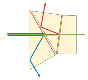
In an imaging prism stack the transmitted wavefront passes through several back reflecting surfaces, see figure 1. In this case there are four potential back reflection surfaces. SCI can measure each of these independently if the surface is of interest, or only the transmitted wavefront without corruption. This allows a straight on measurement without tilting or distorting the wavefront.

Displacement Measuring Interferometer Components
Interferometers for displacement measurement typically have multiple channels for the test and reference beam path. SCI enables the measurement of each channel independently, without the degrading influence of multiple entry and exit surfaces. To select the measurement channel cavity the polarization is rotated by 90º from one to the other, which is accomplished at the interferometer. [A linear polarized interferometer, where the polarization can be rotated, is used for this application. Contact ÄPRE for more information.]

RGB Prism Combiners
RGB (red-green-blue) prism combiners are particularly difficult to measure. The three channels must be separated to measure each path’s transmitted wavefront, yet optically they are co-axial. With a laser interferometer this is impossible, as all the wavefronts overlap, see figure 3. Plus there are multiple back reflecting surfaces that must be eliminated for an accurate measurement. Each channel can be aligned independently in the long coherence align mode. Then selected in the short coherence mode for accurate measurement.

Interferometer resolution
Many RGB prism combiners are classed as micro-optics with a less than 6 mm clear aperture. Therefore a standard 4 inch (100 mm), zoomed imaging interferometer with ~400µm image resolution or worse at all zoom magnifications, has insufficient image resolution. A minimum of 60 µm image resolution is required to measure the wavefront of a 6 mm clear aperture prism. 60 µm resolution yields a 100 X 100 image resolution across a 6 mm clear aperture.

NOTE: This is not 100 X 100 pixels but image resolution. The camera array must be 2X this or a minimum of 200 x 200 pixels AND the imaging optics must produce an airy disk size of 60 µm. At 100 X 100 image resolution 36 Zernike polynomials are accurately calculated. See Figure 4.
Shown in figure 5 is ÄPRE’s S6|HR interferometer with 15 µm image resolution capable of measuring the transmitted wavefront in components to 1.5 mm clear aperture.

Spectrally Controlled Interferometry Separates the RGB Channels
Again with a laser interferometer the three channels create back reflections simultaneously making the measurement impossible. In the measurement set up (see figure 5) each six prism assembly cavity has three cavity of different optical path lengths. Therefore the distance between the test and reference flat is different for each channel. With SCI each channel is selected one-at-a-time. Typical measurement results with SCI and S6|HR are shown in Figure 6.


Summary
Prisms assemblies are difficult optical elements to measure. Back reflections from multiple surfaces and multiple channels make laser interferometry incapable of making these measurements. SCI offers an easy to use, accurate method to measure these components for the first time.

