

This application note teaches how to measure a spherical surface and introduces setup procedures common to all spherical type parts measurements.
Transmission or Fizeau Sphere (TS)
Precise alignment of the TS is required to minimize errors. A misaligned TS, when the TS optical axis has tilt relative to the optical axis, will cause the returning beam to pass through the interferometer off axis. Off axis beams pick up retrace errors lowering the measurement accuracy. This is especially important with continuous zoom imaging systems yet not as critical in ÄPRE’s S-Series interferometers.
Please refer to the Application Notes:”How to Align a Transmission Flat/Sphere” and “Selecting a Transmission Sphere” to select the best matching TS f/# for the spherical lens surface to be measured.
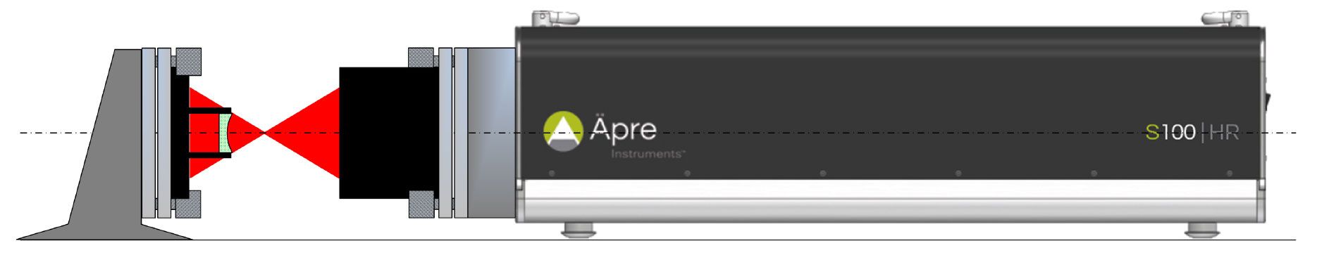
Figure 1: Basic Setup for measuring a concave sphere
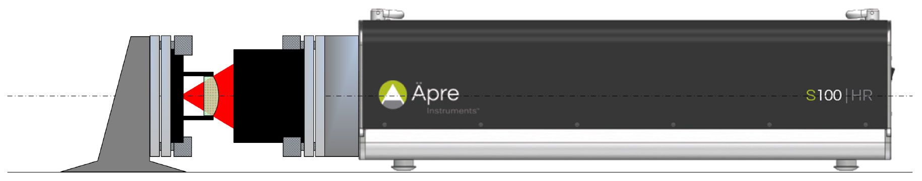
Figure 2: Basic Setup for measuring a convex sphere
Test Part Alignment – Concave Part
Test Part Alignment – Convex Part
Test Part Focus
Focusing the interferometer is important to achieve accurate measurements. Please refer to the application note, “Focusing an Interferometer.”
Averaging might be desired, especially if the environment produces some vibration or air-turbulence
— Expect noise reduction proportional to a square root of the number of measurements
— The improvement limit is when interferometer variability dominates the measurement
In the software analysis, for a sphere nominally only remove TILT and POWER
— Removal of more terms are often used to investigate higher spatial frequency errors
Set the clear aperture to report the specified area of the spherical surface
— Set either the auto-aperture for circular parts, manually create an include mask to include the clear aperture or set the erosion filter to remove unwanted edge errors and pixels outside the clear aperture
With REVEAL you can now click on reports and print out a standard or custom report of the measurement results.
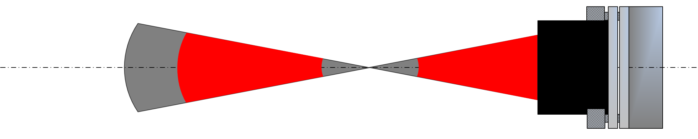
Focus Range within the Spherical Cavity Determines the Range of Measureable Parts
The region where focus is achievable with a TS is limited by the interferometer’s range of focus and the f/# of the TS. See figure 5 as an example. The interferometer typically has ±2 meters focus range. In the image space of the TS this translates into a region starting at the reference surface and ending BEFORE
the TS focus (cat’s eye position) and then beginning again a distance AFTER
the focus position and ending a further distance beyond this.
NOTE: The useful range of radii that a TS + Interferometer combination can
measure is defined by this disjointed measurement space. (see figure 4)
When measuring outside this focus region errors occur, including:
The most common error is measuring parts too small for the interferometer and thus in the region near the TS cats eye position. Since the parts are small the edge diffraction errors cover a large percentage of the parts surface.
Each TS + Interferometer has it own best focus region that must be found empirically, though a “rule of thumb” is the surface radius of curvature should not be less the 20% of the TS distance from the reference surface to the focus position.

