Measuring a flat is a basic interferometer measurement.
This application note teaches how to measure a flat and introduces setup procedures common to interferometer measurements.
A few measurement challenges and solutions are addressed.
Tools Needed
Interferometer
Transmission or Fizeau Flat (TF)
Corner Cube Retroreflector
2 or 5 axis mount with 3 Jaw Chuck or equivalent
Flat to be tested
Setup
Transmission or Fizeau Flat (TF)
Precise alignment of the TF is important to minimize errors. A misaligned TF, any non-orthogonal tilt relative to the optical axis, will cause the returning beams to pass through the interferometer off axis. Off‐axis beams pick up retrace errors lowering measurement accuracy. This is especially important in interferometers with continuous zoom imaging systems yet not as critical in ÄPRE’s S‐Series Interferometers.
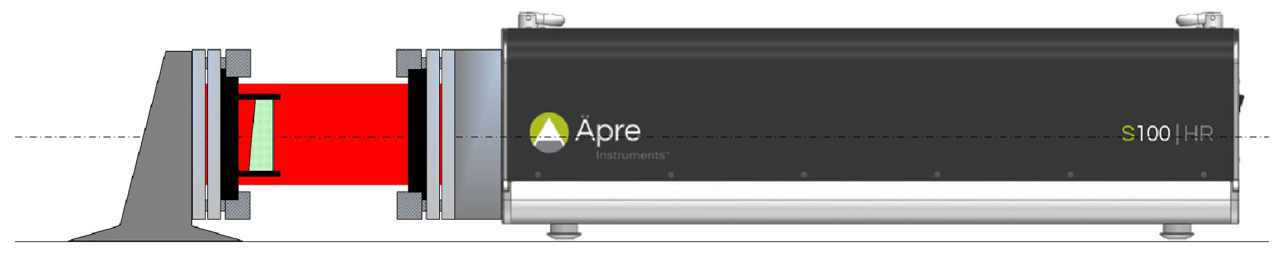
Figure 1: Basic setup for measuring a flat
Rough Alignment of the Transmission or Fizeau Flat (TF)
Mount the Transmission Flat into the interferometer, remove any test part or Reference Flat
Open the alignment screen to view the alignment camera.
a.In some older interferometers there is an “Align/View” switch which mechanically redirects the beam to the
same camera.
Adjust the tip and tilt on the front of the interferometer bayonet mount until the reflected beam off the TF is in the
center of the alignment target.
a.Be careful not to confuse the reflection from the first surface of the wedged TF.
b.This reflection is usually of lower intensity due to this surface being AR coated.
Rough Adjustment is complete.
TF Fine Alignment
Switch to the measurement camera view (or View mode).
Place the Corner Cube Reflector in front of the interferometer in the test beam.
Observe the fringes produced between the TF and retro-reflected beam.
Fine adjust the tip and tilt until the observed fringes are as close to null, or symmetric about the vertex of the
corner cube apex.
The flat is now aligned
Test Part Alignment
Mount the optic to be tested in the fixturing provided
Switch the interferometer into the alignment mode
Adjust the test part until its return reflection spot is centered on the alignment target and overlays the reference spot
Switch to the measurement camera view (or View mode).
Adjust the tip/tilt of the TEST flat (do not adjust the TF!) until the fringes are as null as possible.
Leaving tilt fringes in the measurement can induce retrace errors, especially on continuous zoom systems.
Test Part Focus
Focusing the interferometer is important to achieve accurate measurements. Please refer to the application note, “Focusing an Interferometer”
Measurement
Click the measurement icon to start a measurement.
— Averaging might be desired, especially if the environment produces some vibration or air-turbulence
Expect noise reduction proportional to a square root of the number of measurements.
The improvement limit is when interferometer variability dominates the measurement
— In the software analysis, for a flat remove only TILT.
— Set the clear aperture to report the specified area of the flat
Set the edge erosion filter to remove unwanted edge errors and pixels outside the clear aperture
Or set an include mask to only include the specified area.
Report
With REVEAL you can now click on reports and print out a standard or custom report of the measurement results.
Figure 2: Back surface reflection interference
Potential Measurement Challenges
The main challenge in measurements of an optical flat is the presence of
unwanted reflections from the back surface of the measured part, causing multiple interference fringes, see figure 2. These extra fringes will degrade the measurement and potentially make the measurement impossible.
Methods to Suppress Back Reflections
Wedge the Flat: Manufacturing a sufficient wedge into the flat component
will aim the beam reflected from the back surfaceout of the interferometer
imaging system. Then only the aligned surface will be measured.
Decrease the Back Surface Reflection: This approach requires an additional
optical element with matching refractive index to be placed in contact with the
back surface in an effort to reduce reflection from this surface. The following
methods are known to work, although none of them fully suppress
the reflections:
Grease: A thin layer of grease smeared on the back surface
Paint: Typically black paint is applied
Other: Many optical shops have their favorite method but the principles
are the same
Acquire data at many wavelengths: Typically a scanning laser is used to sweep many wavelengths. After the long acquisition the data is analyzed via a Fourier transform. The frequency of fringe modulation (blinking in and out) depends on the interference cavity length. Faster are longer, slower shorter. After “finding the cavities” the surfaces of interest are reported.
“Short Coherence” Interferometer: Most Fizeau interferometers use lasers as their light source. Lasers create fringes everywhere, hence the back surface interference. Using a broadband source (white-light-like) the interference fringes only occur over a short distance, isolating the surface of interest. Isolation is good but setup is very difficult since fringes are hard to find.
ÄPRE Spectrally Controlled Interferometry (SCI): SCI controls the source
coherence and position of the fringes. Therefore alignment is easy like a laser
interferometer. Coherence can be narrowed down to as little as 50 µm,
isolating the thinnest parts. Plus it can phase measure cavities as thin as
50 µm, making the total thickness variation of waveplates and thin
windows possible.
Figure 3: SCI suppresses back surface reflection interference for accurate measurements
Summary
The measurement of flat components is the simplest measurement with an interferometer. The basics of alignment and measurement are shared with all measurements. Some measurement challenges were discussed with strategies to overcome to always achieve excellent measurements.