

Transmitted wavefront is a functional test, combining the entry and exist surface shapes, their relative wedge, total thickness variation and homogeneity of the bulk material.
The setup for transmitted wavefront is similar to measuring a flat part. Refer to Figure 1 for the basic set up geometry. A flat cavity is setup and then the part to be tested inserted for testing. Therefore the setup begins with adjusting the transmission flat correctly. Please refer to application note “How to Align Transmission Flat/Sphere” for this procedure.
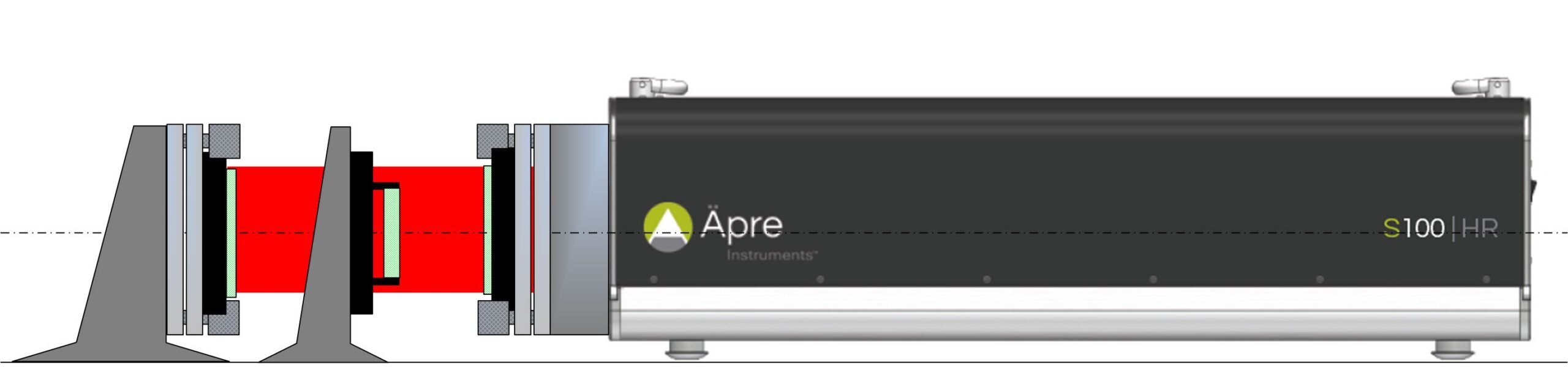
Figure 1: Setup for measuring transmitted wavefront
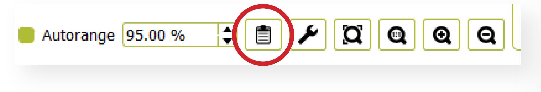
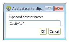
The now set up TF to RF cavity is the reference to which the transmitted wavefront will be compared. To maximize the measurement accuracy this cavity error can be easily saved and subtracted from the actual transmitted wavefront measurement. This is recommended to maximize the performance of this test. The instructions below refer to Äpre Instruments REVEAL™ software.

It is recommended that the Test Part have a smaller aperture than the reference cavity aperture. This is due to the diffraction present at the edge of the reference cavity. This diffraction is caused by not being able to focus on the Test Part and Reference Flat simultaneously. Setting focus is discussed below.
Focusing the interferometer is important to achieve accurate measurements. When measuring transmitted wavefront the Test Part is imaged twice, when the light is going out and when it is returning. These two images are in different image planes. Therefore it is impossible to focus on the Test Part. The proper focus position is the Reference Flat. Therefore find a Reference Flat edge or place a card on its surface to focus on. Please refer to the application note, “Focusing an Interferometer” for a procedure to follow.
To minimize diffraction effects at the Test Part, move it as close as possible to the Reference Flat, which is the plane of focus. This will bring the outgoing and returning images as close to each other as possible.
With REVEAL you can now click on reports and print out a standard or custom report of the measurement results
If the Test Part is aligned with the front or back surface displaying fringes, the measurement accuracy will be degraded or impossible to measure. It is not possible to suppress these back surface reflections with grease or paint, as the transmitted wavefront is required. Therefore the part must be tilted to eliminate these fringes from the measurement, WHEN A LASER SOURCE is used.
Alternatively SCI can be used with a fully aligned Test Part to measure the front and back surface form relative to the TF, internal Fizeau to measure the wedge and relative surface form front to back and then the transmitted wavefront of the Test Part. All this without moving the part from the initial set up.
Alternatively a scanning laser with Fourier transform analysis could be used to
perform a similar measurement, IF the optical paths are greater than 9 mm length. Windows and filters are typically thinner than 9 mm OPL and therefore these techniques are not applicable.
Transmitted wavefront is an easy measurement as long as care is taken to calibrate the cavity, focus on the Reference Flat and move the Test Part close to the Reference Flat to obtain the best results. New SCI technology can aid in simplifying the measurement plus obtaining additional information without moving the Test Part.

