

ÄPRE SCI technology separates the faces enabling easy measurement of all faces, angles and transmitted wavefront.
Fast & Accurate Spectrally Controlled Interferometry (SCI) Prism Measurement
Measurement of a right angle prism is optically equivalent to measuring a flat with multiple surfaces. Typical parameters to measures are:
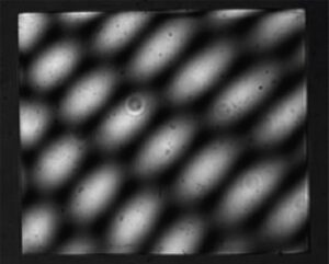
A laser Fizeau interferometer cannot make these measurements due to the multiple reflections off the faces, which degrade accuracy or inhibit measurement, as shown in figure 1. This application will demonstrate how to set up the measurement and use ÄPRE’s Spectrally Controlled Interferometry (SCI) to make possible prism characterization.
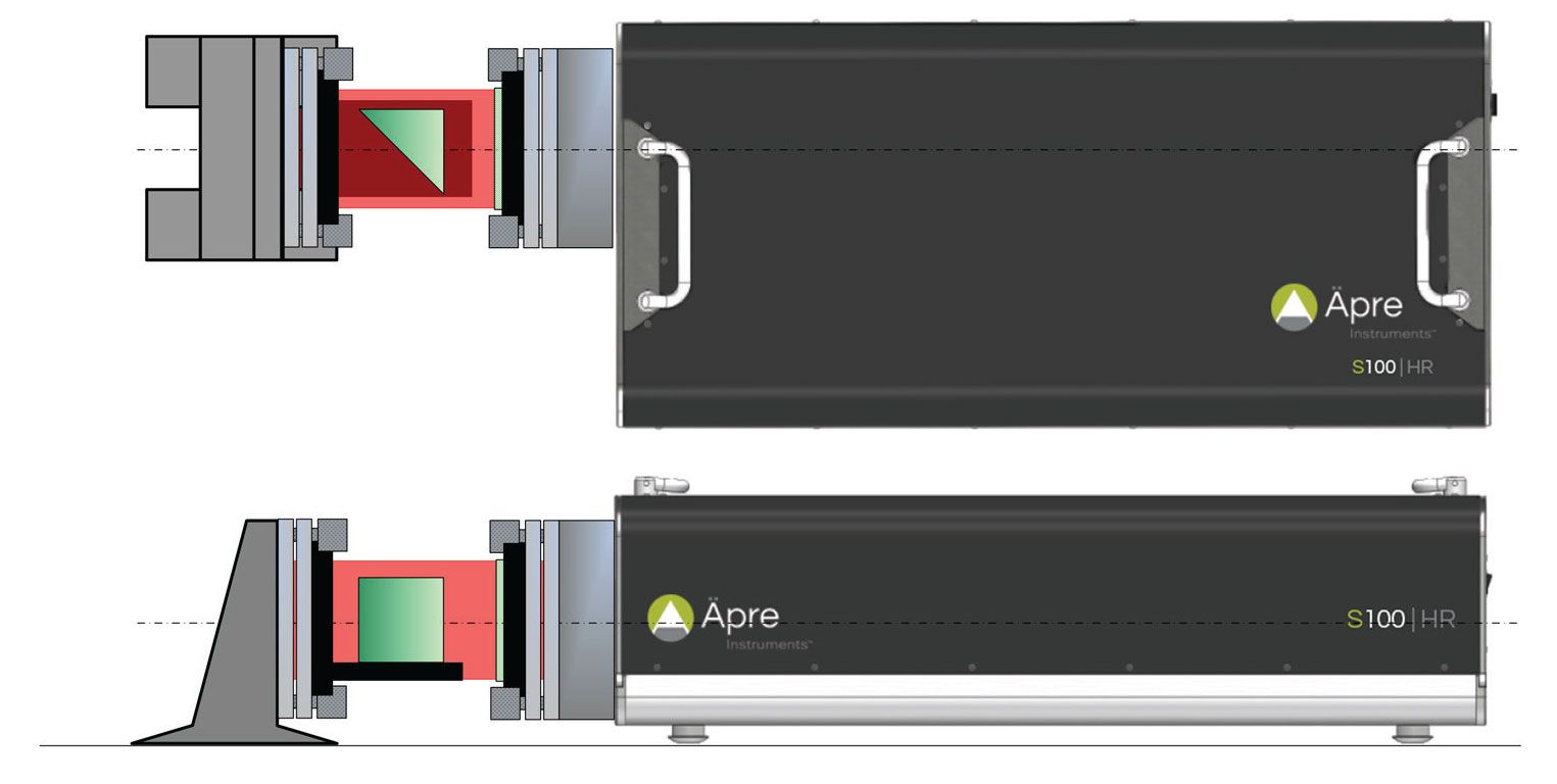
Figure 2: Four measurements of a prism
Precise alignment of the TF is required to minimize errors. A misaligned TF, any non-orthogonal tilt relative to the optical axis, will cause the returning beam to pass through the interferometer off axis. Off axis beams pick up retrace errors lowering the measurement accuracy. This is especially important with continuous zoom imaging systems yet not as critical in ÄPRE’s
S-Series interferometers.
Please refer to the application notes: > “How to Align Transmission Flat/Sphere” to properly align the TF
For the Right Angle Prism always focus on the surface under test.
Please refer to the application note: > “Focusing an Interferometer”
To measure each surface the SCI source is adjusted to narrow the interference width to ~100 um width. This width easily isolates each surface from the other.
NOTE: Micro-prisms are not a problem as the coherence width can be narrowed to 50 um, meaning a 200 um-sized prism is possible to measure, with an appropriately sized interferometer. Further even for small optical path lengths, down to 50 um, SCI can phase measure and acquire excellent surface and cavity data.
Now the interference pattern is adjusted to match the Optical Path Length (OPL) from the TF to surface 1 using the user interface controls. The position should be adjusted for maximum contrast, where a visual estimation is sufficient. Now simply click on measure and record your results for Surface 1, see Figure 3 for typical surface 1 results.
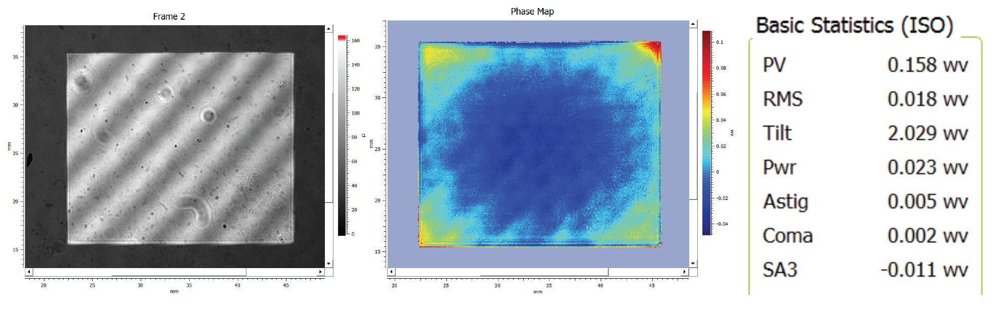
Figure 3: Transmission Flat to Surface 1
Without moving the prism, simply use the user interface to move select the TF to Surface 2 cavity OPL. Again the position should be adjusted for maximum contrast, where a visual estimation is sufficient. Now simply click on measure and record your results for Surface 2, see Figure 4 for typical surface 2 results.
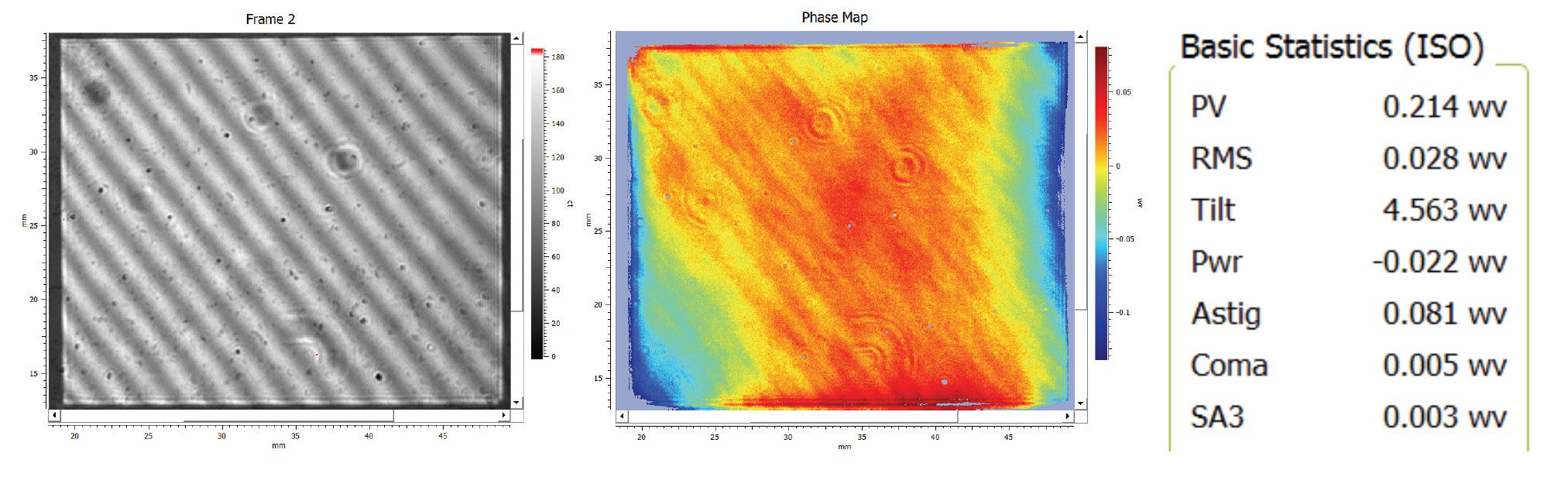
Figure 4: Surface 2 results for Right Angle Prism
Without moving the prism and no changes in the set up, use the user interface to adjust the SCI to the OPL of the Surface 1 and Surface 2 cavity. Now simply click on measure and record your results for Surface 2, see Figure 5 for typical results.
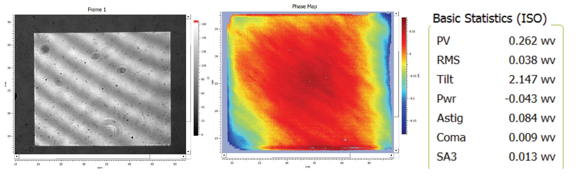
Figure 5: Surface 1 to Surface 2 Parallelism results for Right Angle Prism
Change the setup so the hypotenuse is presented to the TF. Set the SCI source in the alignment mode and align the cavity. Now change the SCI source to the measure mode, adjust the cavity spacing in the SCI source and acquire the data. Typical results are shown in Figure 6.
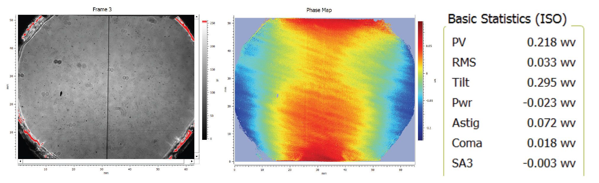
Figure 6: Hypotenuse surface form of Right Angle Prism
Previously difficult measurements of Right Angled Prisms are now possible with the spectrally controlled source (SCI). With the narrow coherence and easy setup even micro-prism measurement is possible.

