

This application note guides you through a deterministic method to assure you have the best focus possible.
Focus is often seen as a secondary procedure in the setup of an interferometer test. With today’s diffraction limited imaging systems focus is now critically important to gaining maximum image resolution and even obtaining the correct form measurement. The described focusing procedure applies to all measurements, figure 1 shows a typical setup, in this case the measurement of a flat.
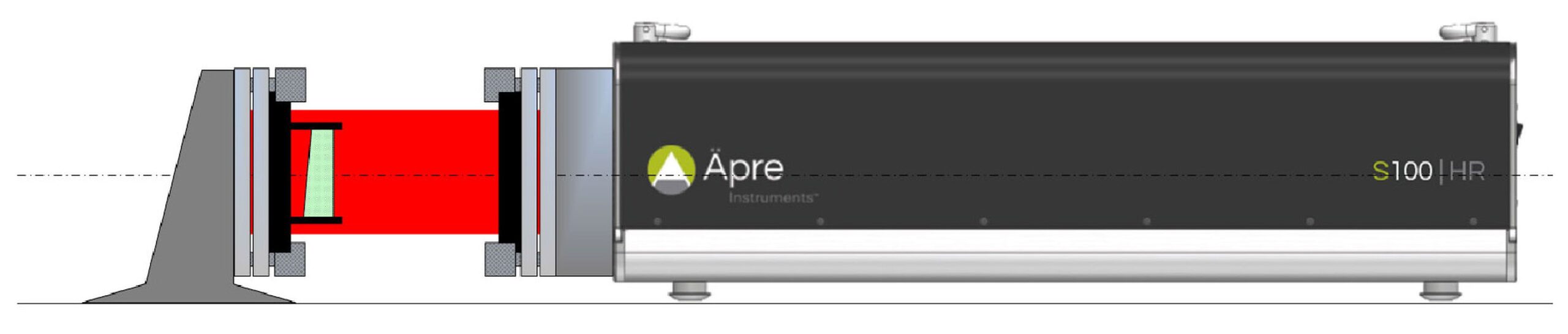
Figure 1: Typical Setup, here measuring a flat
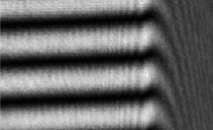
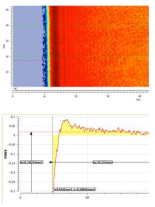
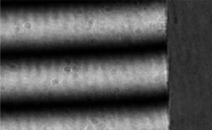
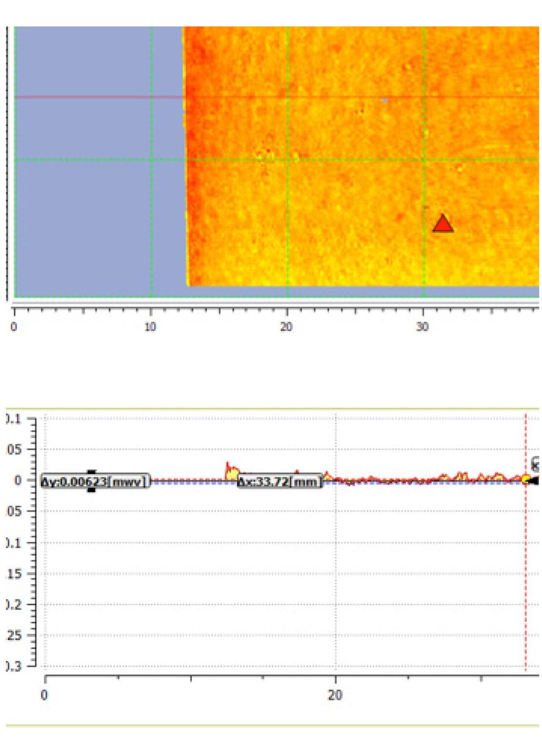
An out-of-focus interferometer will exhibit edge diffraction that measures as a error on the part edge shape or form, see figures 2a and 2b. The more out of focus the larger the edge zone peak-to-valley error will be produced and the deeper into the part the error will appear. Another way to say this is the higher and wider the error zone will be.
The higher the interferometer image resolution the more important is image focus and the more sensitive the focus. Low resolution interferometers, such as continuous zoom systems, can have a “soft focus”, yet the diffraction effects at the edges still degrade the measurement. Historically interferometers are focused visually, this is not recommended for high resolution modern interferometers, visual focus is considered rough focus.
Remove Residual Edge Errors with Erosion Filter
One error correction method is to erode the edge pixels to remove residual edge errors due to imperfect focus (found in REVEAL, open the universal tool bar > open the side bar to the far left of the opened window > filters > erosion or “trim” in other software packages). The physical size of the out of focus diffraction zone is the same for any out-of-focus interferometer no-matter the camera resolution. So more pixels will require trimming for higher resolution cameras to erode the same focus induced edge error.
Note regarding Small Parts
Since the size of the out-of-focus error region is the same for small parts the
clear aperture is easily affected. Therefore for parts with less clear aperture
the margin at the edge, and particularly for small parts, best focus is even more important to achieve.

