How to Align Transmission Flat/Sphere

Aligning the transmission flat and transmission sphere properly is important to achieving accurate measurements.

This step by step procedure assures the reference element is correctly set up to optimize its and the interferometer’s performance.

Tools Needed

  • Interferometer
  • Transmission or Fizeau Flat (TF)
  • Transmission or Fizeau Sphere (TS)
  • Corner Cube Retro Reflector
  • Test lens

Aligning a Transmission Flat (TF) or Sphere (TS)

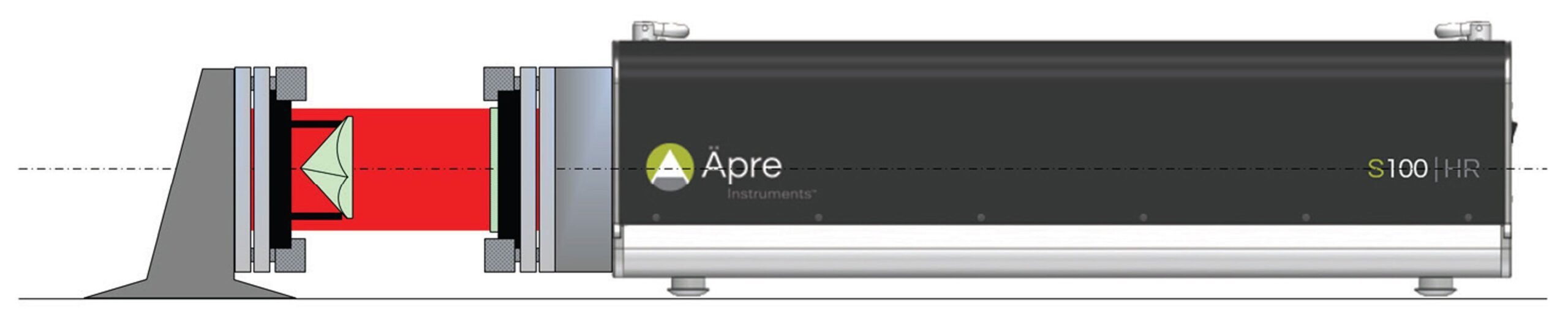
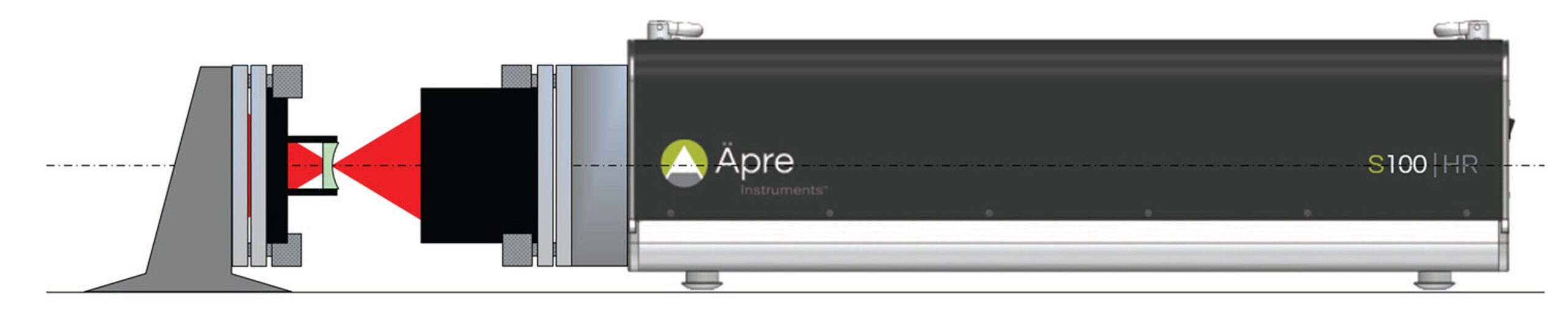
Precise alignment of the TF or TS is important to minimize measurement errors. A misaligned TF/TS, any non-orthogonal tilt relative to the optical axis, will cause the returning beams to pass through the interferometer off axis. Off‐axis beams pick up retrace errors lowering measurement accuracy. This is especially important in interferometers with continuous zoom imaging systems yet not as critical in ÄPRE’s S‐Series Interferometers.

Rough Alignment of the Transmission Flat

  1. Mount the Transmission Flat into the interferometer, remove any test part or Reference Flat
  2. Snug, but do not tighten the locking nuts on the bayonet mount.
    1. Tightening will warp the TF reference surface degrading accuracy
  3. Open the alignment screen to view the alignment camera.
    1. In some older interferometers there is an “Align/View” switch, which mechanically redirects the beam to the same camera.
  4. Adjust the tip and tilt on the front of the interferometer bayonet mount until the reflected beam off the TF is in the center of the alignment target.
    1. Be careful not to confuse the reflection from the first surface of the wedged TF.
    2. This reflection is usually of lower intensity due to this surface being AR coated.
  5. Rough Adjustment is complete.
Figure 1: Set up to align the TF using a corner cube retro reflector

Fine Alignment of the Transmission Flat (TF)

  1. Switch to the measurement camera view (or View mode).
  2. Place the Corner Cube Reflector in front of the interferometer in the test beam (see figure 1)
  3. Observe the fringes produced between the TF and retro-reflected beam.
  4. Fine adjust the tip and tilt until the observed fringes are as close to null, or symmetric about the vertex of the corner cube apex.
  5. The flat is now aligned
Figure 2: Set up to fine align the TS using the cats eye position
Figure 3: Cat’s eye interferogram

Aligning a Transmission Sphere

Rough Alignment of the Transmission Sphere (TS)

  1. Mount the Transmission Sphere (TSS) into the interferometer
  2. Snug, but do not tighten the locking nuts on the bayonet mount.
    1. Tightening might warp the TS reference surface degrading accuracy
  3. Open the alignment screen to view the alignment camera.
    1. In some older interferometers there is an “Align/View” switch, which mechanically redirects the beam to the same camera.
  4. Adjust the tip and tilt on the front of the interferometer bayonet mount until the reflected beam off the TF is in the center of the alignment target.
  5. Rough Adjustment is complete.

Fine Alignment of the Transmission Sphere (TS)

  1. Switch to the measurement camera view (or View mode)
  2. Move the test part into the interferometer beam and position the surface at the focus of the TS. This is the cat’s eye position (see figure 2). You will know you are at cat’s eye because the interferogram will not change significantly as the part is translated in X & Y. (see figure 3 for how a cat’s eye interferogram appears)
  3. Adjust the tip and tilt on the TS until the cat’s eye interferogram is well balanced as shown in Figure 3.
  4. The TS is now aligned
Need more help? CONTACT US
Apre Instruments LinkedinApre Instruments Youtube
+1 520.639.8195

© 2024 Äpre Instruments / All Rights Reserved. Privacy Policy | Design by CleanClearCreative.com