Optical System Alignment and Wavefront Measurement – Buyers Guide Chapter 4

In this blog the alignment of optical systems with a Fizeau interferometer is discussed.

The goal of a system wavefront test is alignment and confirmation of system performance. The measurement of optical system wavefront often requires a custom interferometer. When a fully reflective system is measured a standard HeNe laser Fizeau is sufficient as the wavelength does not matter.  For refractive systems the wavelength often must match the optical system design, and optical system wavelengths vary from 10.6 um to 193 nm.  Thus these systems are often “custom” except for a few wavelengths that are more common. For this discussion the wavelength is assumed to be matched to the system.

Zernike polynomials are often used to define system wavefront errors during alignment

Null Test

If a null, adjust until near-zero error is the goal then a standard continuous zoom system can be sufficient.  At null ray trace errors are minimized and wavefront imaging distortion error minimal.  Further mid-spatial frequency errors are not critical when measuring system alignment. Some of these measurements are made with a null corrector lens that matches the system under test wavefront with the interferometer expected wavefront, either spherical or plano.

Non-Null Testing

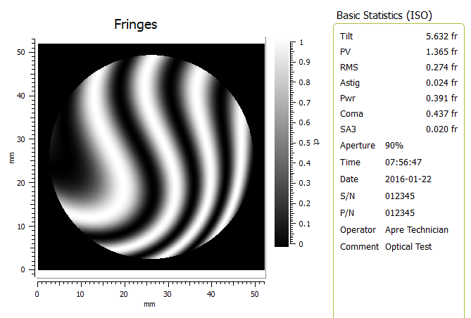
Subsystem testing can produce non-null wavefronts in the final alignment.  For non-null system an interferometer with low ray-trace errors is important. With high fringe density, or high slopes, ray trace errors grow. Ray-trace errors are developed when the test and reference wavefront traverse diverging paths to the camera and are seen primarily as coma and astigmatism, with sometimes spherical errors.  If the final “aligned” condition is at 10 waves of spherical aberration then unless the interferometer is well corrected for ray-tracing errors the data will exhibit errors in final alignment.

Precision alignment is important for optimal optical system performance, especially with more complex optical paths.

Small systems

A bench top system test is similar to measuring an optical component and standard phase shifting data acquisition is sufficient.

Real Time Adjustment

Recently the introduction of widely available simultaneous data acquisition interferometers have enabled near real time phase.  So alignments can be adjusted continuously for more rapid convergence on alignment.  
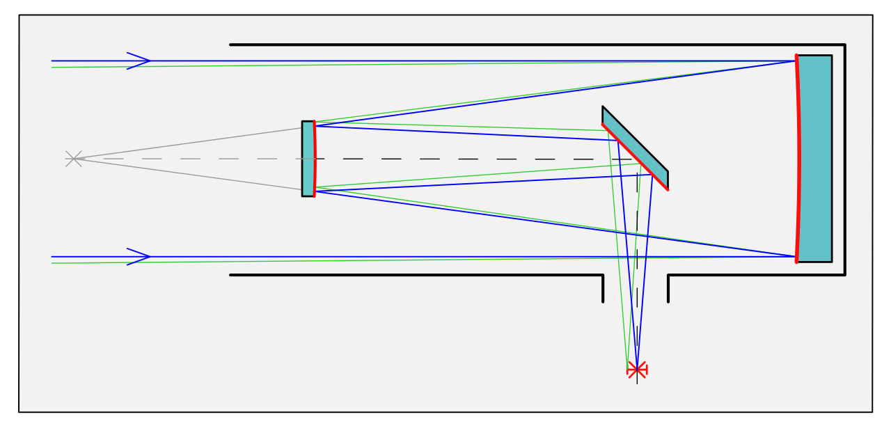
Large Systems

For large systems, typically telescopes, vibration and turbulence become an issue. If an issue then only a simultaneous phase measuring system will be able to acquire data.

Summary

In most cases a standard interferometer with near matching wavelength is sufficient to test optical system wavefront. Where large or non-nulled cavities are involved a high performance interferometer with low ray-trace errors and/or simultaneous phase measurement need to be used.

Next Post: Small tool polishing applications

Lap Polished Flats, Spheres and Prismatic Components – Buyers Guide Chapter 3

In this blog the measurement of optics with a Fizeau interferometer that have been lap polished is discussed.

What interferometer is needed to produce good parts? Each manufacturing process requires a specific measurand, the quantity to be measured, to provide the feedback necessary to control the process and produce good parts.  In the following posts several applications will be discussed with optional systems highlighted. 

Random, Near of Full Sized Tool Polishing

Classic Spindle Polisher/Grinder

The historic method to manufacture optics has been random polishing on a spindle polisher.  The procedure of rough forming the surface

shape, grinding to near polish and then lap polishing has been used for hundred of years.  The beauty of lap polishing is the random nature, averaging over large areas of the sphere, which self corrects, and lead to high quality surfaces.  Further the mid-spatial frequency ripples, the residual surface features remaining after the removal of 36-Zernike polynomials, tends to be suppressed due to averaging. There are limits and caveats as always, yet in general these are reasonable assumptions. Thus the measurand is simply the shape of the surface as defined by 36 Zernike polynomial coefficients. 

The Old Zygo® Mark II Optics Sufficient

Since the meaurand is simply low spatial frequency shape, in this application, a continuous zoom imaging interferometer, with the inclusion of phase measurement is sufficient. This is why the Mark II architecture as been useful for over 35 years, it was sufficient for nearly all optics produced until this century. The low spatial resolution of the imaging system (no matter the camera resolution), and inherent image distortion of the zoom lens up to ~2%, and slope induced errors have little effect on measurement uncertainty of flats and spheres when measured at a null fringe condition.

Vibration Tolerant Data Acquisition Important

More important than the optical system for this application is the data acquisition and analysis software. This starts with vibration tolerant phase data acquisition as found in modern systems to report phase data without the influence of the production environment vibration. (We plan to discuss the history and development of vibration tolerant PSI in a future blog.) Further the software must be compatible with standard industry standards including ISO and data formats (.dat formats), and be easy to use.

Upgrading an Old Interferometer Is a Good Option

To stay current and meet the the requirements of lap polished optics there are two choices: Buying new or upgrading. The first option is purchasing a newly constructed system with classic optical components that has a new data acquisition system. The second is simply upgrading a classic system to a modern data acquisition system (with vibration tolerant algorithms). The performance of each will be equivalent, with the upgrade being much less expensive.

Summary

Lap polished Flats, Spheres and Prisms in a normal production environment are sufficiently measured with a continuous zoom system, where the value choice is often a system upgrade.  

In the next post we’ll explore what is an appropriate interferometer for transmitted wavefront measurement.

Fizeau Interferometer Buyers Guide – Chapter 1

The many laser Fizeau interferometer choices make selection confusing.

You don’t want an laser Fizeau interferometer. You just want optics that meet specification, and your Fizeau interferometer helps you do just that.  Yet choosing the right interferometer can be confusing.  Just consider the choices:

Data Acquisition

  • PSI, IPMI, or Carrier Fringe, or wavelength tuning, vibration insensitive, vibration tolerant, multi-surface, scanning Fizeau, stitching…

Illumination

  • high-coherence, low-coherence or partial coherence (ring)

Wavelength

  • 633nm, 1.06um, 3.39um, 1550nm, 10.6um, 650nm, and many others.

Imaging

  • zoom, discrete, and fixed magnification, plus ground glass or coherent

Detectors

  • 256K, Mega or multi-mega pixel detectors, and then their is CCD or CMOS

System Configurations

  • Common path, off-axis, high-slope, steep surface, mid-spatial frequencies

Software Analysis

  • Zernike, slope, ISO, masking, frequency filters, box filters, and a plethora of others

Applications

  • wavefront, surface, radius of curvature, homogeneity, wedge, corner cubes and …  

The combinations are hard to keep track of let alone configure to your specific requirements and budget. So over the next few weeks we will be running a series of blogs to offer some guidance and insight regarding what is important depending on your application.

In the next post we’ll set the stage with a brief history of optical test interferometry.