Case Study: Interferometer Boosts Guernsey Coating’s Capabilities and Growth Opportunities

Guernsey Coating Labs, a Ventura, CA-based company has supplied optical thin film coatings to the industry for over 40 years. Guernsey recently purchased a Zygo interferometer with an Äpre software upgrade. Ty Guernsey, President and Founder, shares how this has assisted in expanding capabilities for her company.

What challenges led you to invest in interferometry?

The interferometer lets us control the whole process reducing our customer’s risk.

Guernsey Coating Laboratories is an optical coating house with the mission to support our client’s needs. Working with our clients, we can now provide substrates on their behalf. A complete product (substrate plus coating) has been beneficial for many clients since it saves them extra time and steps in having to buy glass separately.

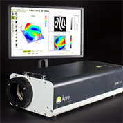
In the past, it was up to the client to take the responsibility for surface flatness. With our Varian spectrophotometer, Zygo interferometer, with Äpre’s 1MP camera, computer, and software upgrade, our clients can have more data regarding their product with precision information even before the finished optic is delivered.

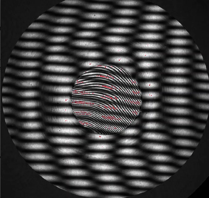
The interferometer lets us measure the flatness of the substrate prior to and after coating. This helps during the inspection process in order to reduce our customer’s risk.

We can now determine whether the substrate is up to the flatness standards required pre-coating as well as the surface figure properties after coating is applied.

Surface quality of the substrate (as in under-polishing, scratches, digs) is imperative prior to production. However, it is also known within the industry that flaws are enhanced after coatings are applied. Using the interferometer will only determine the flatness.

Why did you choose Äpre?

Äpre’s open communication made the purchase straightforward.

Äpre was able to install software quickly, efficiently, and within a price point that made sense. Äpre also made the logical experience a breeze.

Did you look at alternative optical metrology solutions?

This interferometer and software upgrade was a great fit for our needs, driven by our customer requirements.


”Watching Guernsey Coatings’ success is so rewarding. Their interferometry system and software aren’t just another tool – it’s a way they live out their company mission by adding more value.”
Robert Smythe, President, Äpre


What were installation and training like?

Äpre made the software installation easy and uncomplicated.

Although using the software was more of a learning curve, it was definitely not extensive. We’re very fortunate to have expert employees, some of whom have been with us for decades. They are cross-trained on our upgraded equipment making sure we keep projects going even when someone is on vacation.

What’s next for you and Guernsey?

With Äpre’s open communications and great rapport, we’ll continue to work together. I’ve been extremely happy at every point along the way.

It has been beneficial for us as well as our clients to have the interferometer added to our capabilities. When a client requires Guernsey to supply a substrate, we can now check the flatness of the glass, taking that responsibility off of the client. Any instrument that assists in providing an improved product is vital to the success of our client.

The field of thin film deposition is not without its’ challenges. Communication and transparency between ourselves as well as our clients is a foundation we strive to keep.


At ÄPRE we’re keeping our eyes on the horizon to boost your capabilities and profitability. Let us provide you with state-of-the-art systems to advance your process. Contact us today to get started.

Spectrally Controlled Interferometry – Wins Prestigious Award

ÄPRE’s Spectrally Controlled Interferometry was awarded one of Laser Focus World’s highest awards for innovation in photonics, a Gold-Level Honoree.

We are proud to be recognized by this leading industry journal for the innovation that SCI brings to optical testing.

Even more exciting is hearing from our customers how SCI saves time and money as plates do not require painting or wedging to measure, and miniature optics are finally measurable with an interferometer!

Plus it can be added to ÄPRE’s S-Series interferometers now or in the future as they are SCI ready, or your old interferometer can be upgraded with an SCI source.

Contact us to learn more.


Laser Munich 2017

Jan Posthumas of LaserPeak (on left) and Don Pearson, ÄPRE’s VP Sales (on right)

Don Pearson, our VP Sales and Jan Posthumas, of LaserPeak (ÄPRE Representative) presented ÄPRE’s S100|HR interferometer in Munich this June. Once again we were pleased to meet with, and make new friends while co-exhibiting with the PTB’s HLEM (Hi-Level Experts Meeting) group.

Presented was the S100|HR, part of ÄPRE’s S-Series interferometers with diffraction limited imaging to 50 µm resolution (S50|HR), and all with <0.1% image distortion and <λ/20 retrace errors even at 6.5 fringes/mm.

We were also pleased with the interest in our new SCI based system that electronically remove back reflections from measurements and we look forward to discussing this more in the future.


Photonics West 2017 Introductions

Don Pearson, VP Sales and Takuya Mikami of Okamoto Optics Works discuss ÄPRE’s S100|HR interferometer

It was great to meet many new and old friends in San Francisco at Photonics West. Tradeshows give all of us an opportunity to discuss the challenges and opportunities facing us and discovering how working together we can help each other. Photonics West was no exception.

This year we introduced the latest member of ÄPRE, Don Pearson Vice President Sales. Don comes to ÄPRE with a long history selling and applying interferometers and is known to many in the industry. Previously of Mahr and Trioptics Don is looking forward to meeting you and seeing how we can work together.

We also introduced to Photonics West our S100|HR laser Fizeau interferometer. We are pleased at its reception and how measuring mid-spatial frequencies and form with one instrument is a cost and time savings. Plus accurately measuring 5X more slopes gets the final figuring process started sooner, saving time.

Contact us to discuss how we might work together.

S100|HR Introduced at Optatec

Piotr demonstrates the S100|HR to a visitor

S100|HR Fizeau Interferometer Introduced

The new S100|HR laser Fizeau interferometer was introduced at the Optatec tradeshow in Frankfurt Germany this past week. We are excited by the industry’s response to a high-performance system offered at a fair price, and the continued interest in interferometer upgrades. The S100|HR was displayed measuring in the vibration insensitive mode and performed flawlessly.

This year we co-exhibited with the PTB working group for precision optical metrology. Thank you to Heiko and his team for coordinating the booth set up and the great catering! Everyone was very supportive.

OptoTech GmbH displayed our S100|HR integrated into their new OWI 150 Inverse workstation. This high performance workstation measures radius of curvature over 1 meter and surface figure while using ÄPRE’s REVEAL software in an OEM configuration. This is a great example of the power of REVEAL to automatically read the Z position to measure radius of curvature and to be modified to a specific customers requirement. OptoTech favors a more classic appearance including a dark blue background to be more familiar to users.

Again thank you to all who visited us at Optatec this year.

Our next show is Optics and Photonics in San Diego California.  See you there!

Fizeau Interferometer: Buy or Upgrade; what are the purchasing options?

Fizeau Interferometer Buyers Guide 9

This blog is about the performance and price options for laser Fizeau interferometers

Up to this point we have been discussing how various applications require specific interferometer sensor configurations and features. Now comes the key point when you need to do something. Do you need increased production capacity? Has a new process been introduced that requires better feedback? Is the IT department concerned about an old operating system? Has the computer failed, or the system has become unreliable but meets your production needs? Do you have a new program that requires a dedicated system? Or your customer is pushing for a result your system does not produce. What do you do? Do you buy a new interferometer? What are the options?

Buy New, Upgrade or Buy Refurbished?

Asking some questions can lead you to the purchasing options to consider.

  1. Is the system to support a spot polishing process where slopes and mid-spatial frequencies are important?
    • Yes – indicates a high performance imaging interferometer with a 2K X 2K level camera, low distortion and low ray-trace errors.
  2. Is the environment harsh, with vibration and air turbulence present?
    • Yes – indicates a SPMI (Multi-detector or Carrier Fringe acquisition) system
  3. Does your application require custom fixturing, a special wavelength or non-standard aperture?
    • A custom system is required – talk to the various providers regarding your best option
  4. Does the system support a standard lap polishing process where form is the key measurand?
    • Yes – indicates a classic interferometer

High Performance Imaging System laser Fizeau

These are the latest technology and will meet all the requirements for most situations, the problem is they tend to be expensive. Not only do they image mid-spatial frequencies well, the associated low ray trace errors mean they are suitable for carrier fringe data acquisition for operation in harsh environments. The major drawback is price. Most systems are 1.5X to 2X more expensive than a classic interferometer. If they were the same price everyone would probably buy one of these interferometers.

Harsh Environment laser Fizeau or laser Twyman-Green

There are several interferometers available that meet this need using both carrier fringe and multi-camera or multi-pixel configurations, Many of these applications have specific specifications that dictate size, weight, and result output. It is best to discuss these with the manufacturer to arrive the best choice.

Classic laser Fizeau Interferometer

With the classic Fizeau there are the most choices.

Refurbished miniFIZ interferometer

Buy New or Refurbished: Increase Production Capacity

If increased production capacity is required there are two choices: Buy new or refurbished. There are a few choices for new systems that have the same optical system as produced for the last 30 years – with extensively upgraded software! These new system are priced between $60,000 and $75,000 (USD).

Also available from time to time are refurbished interferometers with the same/similar classical optical design. These refurbished systems have the latest data acquisition and analysis software like a new system and are priced between $33,000 and $37,000.

Upgrade: Failed System, Old Operating System, New Acquisition and Analysis Software Required

There are thousands of interferometers installed worldwide that can be renewed by upgrading the electro-optics and software. These systems can operate as well as a new system, with the latest software, cameras and computer systems. Upgrading is cost effective and is priced between $22,000 and $27,000. Upgrading is usually the best choice when production capacity is not an issue, but systems are down. A side benefit is the increased efficiency of new electronics can also increase the throughput and therefore production capacity of existing systems.

Summary

There are several purchasing options available regarding laser Fizeau interferometers. Applications often drive the decision but price is also important.laser Fizeau Relative Pricing

Measuring Thin Parallel Plates – Buyers Guide Chapter 8

In this blog the measurement of thin parallel plates with a Fizeau interferometer is discussed.

Filters, etalons and plane parallel components exhibit reflections from the front and back surface rendering them impossible to measure in a standard laser Fizeau interferometer. A standard interferometer uses a laser, making interference easy to create, no matter the interferometer cavity length. With parallel plates additional interferometer cavities are created adding confusing fringes: 1) Reference surface to the plate front surface, 2) reference surface to the plate back surface and 3) plate front surface to back surface.

A few techniques are available to overcome this confusion.

Spectrally Scanned Interferometry (SCI) – Click for more information

Laser Fizeau compared to SCI Fizeau – 1 cm substate with 250 um step in the middle.

ÄPRE has introduced a practical SCI source, a new source modality to Fizeau interferometry. SCI controls the coherence, fringe position (over 100’s of millimeters) and phase modulation of the fringes electronically. SCI aligns in high coherence mode, like a laser, isolates like a white light source, positions the fringes within the cavity, and phase modulates regardless the cavity size, even down to 50um. By isolating

the surface of interest, accuracy is improved and new applications are enabled. This is a new technology and its impact will emerge in the coming years.

Wavelength-Modulation + Fourier Analysis

Modulating laser wavelength will change the observed phase of the interference fringes.  The rate of fringe modulation as the wavelength is changed is a function of the interferometer cavity length, long cavities modulate more rapidly than short cavities.  Thus when a wavelength scan is performed and the results Fourier analyzed for modulation frequency the various cavities can be separated. By performing phase shifting interferometry analysis on the now separated surfaces thin parts can be measured, surface by surface. The drawbacks of this approach tend to be price and careful set up. To assure proper extraction, the surfaces must be positioned so the modulations are separable and not overlapped which is not always possible. Some versions also provide absolute position in space enabling millimeter length steps to be measured. 

Short Coherence Balanced Arms

An incoherent source, like a diode, can produce fringes at a location in front of a Fizeau reference flat IF a secondary interferometer system is coupled to it. By adjusting the coupling cavities length the interference fringes are placed in space in front of the Fizeau reference surface. This method produces high quality, single surface fringes where the front and back surfaces of a thin part can be measured. Another short coherence approach is to use a Twyman-Green equal path interferometer and a diode. The main drawbacks of these systems are price and set up. The fringes exist at a specific point in space and the test part must be moved to within micrometers in tip and tilt and Z to simply see fringes. This can be challenging if separate alignment aids are not provided.

Grazing Incidence

By producing a steeply grazing illumination beam and varying the spatial coherence of the illumination, the back surface of a thin part can be eliminated from measurement. This techniques has been used successfully to measure semiconductor masks and sapphire wafers, though it is not used often in optical testing. The steep grazing incidence angle enable even rough surfaces to reflect specularly, with desensitized fringes (5um equivalent wavelength) and therefore the accuracy is not sufficient for most optical work. 


Harsh Environment Testing: Optical Towers and In-situ Metrology – Buyers Guide Chapter 6

In this blog measurement of optics in a harsh environment with a Fizeau interferometer is discussed.

For large systems, typically telescopes, vibration and air turbulence hinder or prevent the measurement phase by temporal phase shifting. Also interferometers placed on machine tools to measure in situ experience a vibrating environment. When vibration and turbulence hinder measurement then only a simultaneous phase measuring system (SPMI) will be able to acquire data. These systems acquire phase data fast enough to freeze fringe motion due to vibration and turbulence.

SPMI Data Acquisition: Multi-Camera and Carrier Fringe

There are two primary SPMI data acquisition architectures: Multi-camera1  and carrier fringe2 .  Multi-camera uses polarization to split the intensity data into multiple images with shifted phases which are analyzed for wavefront phase.  Carrier fringe uses tilt in the wavefront coupled with several different analytical approaches to extract phase. Both approaches are successfully employed commercially, and are functionally and performance equivalent.

Tower for testing large mirrors at the University of Arizona

Averaging is Required

The SPMI system enables phase to be acquired, but the phase is changing rapidly and by large amounts and any single measurement is meaningless. To achieve stable data, averaging must be employed. The amount of averaging required is a function of the frequency and amplitude of the vibration and turbulence. A useful method to determine how much averaging is required is to acquire 100 data sets in a series as would be performed in an average. Calculate the RMS or P-V of this data set, divide the RMS or P-V by the measurement repeatability desired to obtain a ratio.  Square this ratio and set the average to this squared value.  For example, if the single measurement repeatability is 6,000 nm P-V and desired is 60 nm P-V then 1002 averages must be taken, at a minimum, to achieve 60 nm P-V repeatability, assuming a gaussian distribution.  It is often practical to stir the air with a fan to improve convergence, which can take many hours for large cavities with slowly moving fringes. SPMI systems can often acquire and calculate phase in seconds so averaging can be rapid.

Repeatability is Not Accuracy

Finally, note that repeatability is not low measurement uncertainty, or accuracy.  Measurement uncertainty is primarily driven by the optical design of the interferometer, temperature variations in all the optics, mechanical stresses in mountings and optical misalignments and null lenses errors – a la Hubble. Controlling these is much harder than averaging and is a topic unto itself.

SPMI Interferometers are Non-Common Path – Hence Lower Accuracy

Also note SPMI systems are non-common path systems – the polarization paths are different or tilt exists between the test and reference wavefronts. These differing paths degrade the optical performance compared to PMI which can be common path, i.e. the test and reference beams perfectly overlap when a sphere or flat is measured in a nulled condition. So from an accuracy point of view PMI- nulled can outperform SPMI, but when data cannot be acquired due to turbulence or vibration then SPMI is required and an accuracy compromise is acceptable.

Summary

Acquiring data in harsh, vibrating and turbulent environments requires an SPMI data acquisition interferometer. Achieving high accuracy results requires careful attention to the all measurement parameters and is typically of lower accuracy than a nulled laser Fizeau phase shifting interferometer in a quiet  environment.

1 Smythe, R & Moore, R; “Instantaneous Phase Measuring Interferometry”, Opt Eng, Jul/Aug 1984, 25(4):361 – 364

2 Takeda, M. “Spatial-carrier fringe-patter analysis and its applications to precision interferometry and profilometry: an overview, Ind Metrol 1990;1(2):79-99

Spot Polished Spherical and Flat Optical Components – Buyers Guide Chapter 5

In this blog the measurement of spherical and flat optics with a Fizeau interferometer that have been spot polished is discussed.

Spot polishers require improved performance over interferometers with standard 6X continuous zoom imaging

Spot polishing machines for rapid manufacture of standard and high accuracy spheres place new requirements on interferometer systems. The spot polishing method can create small ripple in the surface while shaping the overall form. Accurate positioning of the polishing spot is required to correct the surface errors to bring the surface into specification. To guide the spot polishers image distortion, resolution, and pixel scaling (calibration) are important  These requirements primarily drive the imaging system of the interferometer. Continuous zoom system do not meet these requirements.

Modern Imaging Systems

Modern interferometers have discrete or fixed magnification imaging to improve resolution, and minimize distortion and ray tracing errors. All the interferometer optics are exposed to coherent laser light which highlights surface defects.  Therefore the optics must be high quality to supress bulls eye artifacts (stray fringes) from scratches, pits, dust and reflections. These hight quality optics increase the system cost.

Interferometer Image Resolution

Increased resolution is required to measure mid-spatial frequency surface features. These features can be defined as the residuals present after the removal of 36 Zernike polynomial terms (see REVEAL analysis screen below, the image on the right are the residual mid-spatial frequencies). Mid-spatial frequencies in an optical surface scatters light degrading the image or lowers directed energy concentration. Therefore they must be measured and corrected.

Mid-spatial frequencies are measured with a high resolution imaging system. Typically greater than a megapixel camera is required. The resolution is limited by either the optical design or the camera resolution. If the camera limits then the smallest feature measurable is approximated by 80% of Nyquist frequency
(1-line/mm:2 Pixels), or ~400 lines/aperture for a megapixel camera. At 50 mm field of view, approximately 125 µm feature can be imaged. Continuous zoom interferometers are limited to <100 lines/aperture.

Interferometer Image Distortion

Image distortion maps a surface feature in the wrong position, and the polisher will move to the wrong position. In the best systems the camera limits resolution. As noted 400 lines/aperture is the practical limit of resolution in a megapixel camera, so distortion of 1/400 or 0.25% is required. The polishers polishing function might decrease this requirement, but with 0.25% the interferometer will not be the limiter. For higher resolution cameras the 80% Nyquist again drives distortion… more pixels better distortion requirements, yet practically the polishing function (the shape of the polishing spot) is the limiter. Continuous zoom systems can exhibit up to 2% distortion – 10X higher than modern interferometers.

Interferometer Ray Tracing Errors

When the test part deviates from a sphere many fringes are seen. These fringes indicate high slopes between the reference and test wavefronts. When high slopes occur the test and reference wavefronts traverse different paths through the imaging optics. These divergent paths create wavefront errors in an uncorrected interferometer system. This error can be measured by acquiring data with a null interference cavity, saving the data and then acquiring data with the maximum number of tilt fringes that can be measured and subtracting the two results.  The residual error will primarily be due to ray tracing errors and is seen as coma and astigmatism, and sometime spherical aberration. In the old continuous zoom systems thes

e errors can be as large as a wave of error.  Even for the small amount of slopes they can measure.  

To speed the convergence of the polishing correction process minimizing these ray tracing errors are required. Only the highest quality systems are corrected for ray-trace errors.  

Summary

For spot polishing of spherical and flat components a low distortion, high resolution interferometer with low ray trace errors is desired.  

Next Post: Next we discuss special applications, starting with Harsh environments