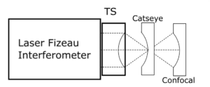
Optical surface radius is a primary control parameter. It must be measured to confirm the optical element meets specification. Spectrally Controlled Interferometry promises a faster and more accurate method to measure surface radius.
Multiple methods are presently used to measure radius.
- Test plates: A test plate has a pre-measured radius to which the test surface is compared, the difference is power fringes is reported.
- Mechanical probe: The sagitta of the lens surface is measured over a fixed diameter, from which radius is calculated. Small changes in sagitta measurement can lead to large errors in reported radii.
- Interferometer “Cateye to Confocal”: An interferometer with a transmission sphere (TS) is set up at the catseye position off the surface of interest, and position noted. Then the lens is moved to the confocal position and the position noted. The difference in positions is the radius. PMI interferometers also compensate for any residual power in the measurements due to imperfect positioning. The positions are shown in figure 1.
Interferometer radius measurement is the “gold standard” method today. To achieve this measurement the following additional equipment is needed:
- Lens mount that allows for free motion along the axis of the lens (Z axis) to micrometer position accuracy
- Free Z motion over up to a meter, with micro-radian angular alignment to minimize cosine errors.
- A separate Z position metrology tool. Either a glass scale or a displacement measuring interferometer (DMI) The DMI is the most accurate as it minimizes Abbe offset errors, though it adds environmental uncertainty if not calibrated.

Spectrally Controlled Interferometry (SCI) Radius Measurement
SCI has a unique combination of four properties:
- Easy alignment in laser mode
- Electronically switch to white light mode to isolate fringes to the surface of interest
- Measures the cavity phase electronically (no mechanical motions)
- Measures the absolute distance of the measured cavity
SCI Absolute Position Measurement
The SCI source parameters that determine the absolute distance measurement are:
λ0 = The nominal wavelength of the SCI source
Δλ = A tunable source parameter
The absolute distance from the transmission sphere to the optical surface is:
lc = λ20 / 2Δλ (1)
This combination means SCI can provide all the measurements required for surface radius with neither an additional DMI, nor the precision mechanics to move from Catseye to Confocal position.
SCI Radius Measurement
Since SCI can measure absolute position there is no requirement to measure at two positions. For the first time surface irregularity and radius can be measured at the same time. This also improves measurement accuracy by the elimination of several error sources as discussed below.
SCI Radius is measured by first calibrating the radius of the TS = RoCTS. Then directly measuring the cavity length lc with SCI and calculating the part RoCx from:
RoCx = RoCTS – lc (2)

Measurement Accuracy
Repeatability
The foundation of accuracy is repeatability. If a measurement process is repeatable it can then be calibrated to yield accurate results. Repeatability of measurement has been shown to be <0.5 µm for radii in the 20 mm to 175 mm range. This repeatability is better the best measurements with DMI’s.
Accuracy NIST Study
In 2001 NIST ran an experiment to determine the error sources and limits of accuracy for surface radius1. The results of that experiment and error sources are shown in figure 3, along with estimates from Typical DMI and Typical Scale (Glass) radius benches and SCI.
A key observation is most of the error sources are due to measuring the distance between catseye and confocal. In the NIST study fully 90% of the errors are in this part of the measurement. The same is true for the DMI and Glass Scale. The only difference is the magnitude of the errors that are 16X and nearly 500X greater, respectively, than the NIST study.
These values are a precaution to users of a DMI or glass scale radius bench to not underestimate the errors in the measurements.

SCI Eliminates the Z Axis Motion Error Sources
No Z motion eliminates the first six error sources (green). Leaving the balance of the error sources that are equal to the Typical DMI set up. SCI can potentially improve the uncertainty to better than the NIST study.
An additional error source is the calibration of the TS radius that also must be added. Since it can be bootstrapp calibrated to the same level a simple doubling of the errors to ~50 nm is expected.
As of October 2020 SCI can measure surface radius up to 250 nm cavity lengths, and potentially out to 500 mm cavity lengths.
Summary
SCI promises to replace traditional catseye-confocal lens surface radius measurement by saving time and greatly improving accuracy. It is the go to method for high-performance lens radius metrology.
1 T. Schmitz, A. Davies, C. Evans; Uncertainties in interferometric measurements of radius of curvature, Appeared in Optical Manufacturing and Testing IV, H. Philip Stahl, Editor, Proceedings of SPIE Vol. 4451, 432-447, 2001