Failing Good Parts? Maybe the Problem is Retrace Error

Failing Good Parts? Maybe the Problem is Retrace Error

Retrace error is rarely specified for an interferometer, often ignored and can cause good parts to fail. Knowing how to minimize, decreases scrap, saves time, and lowers manufacturing cost.

Transmitted Wavefront Measurements

Recently an ÄPRE upgrade customer using a 6X zoom interferometer noticed unexplained user-to-user variations. The setup was a window within a Transmission Flat (TF)/Reference Flat (RF) cavity. With the window in place, the operator adjusted the tilt fringes using the reference flat to a user selected number of tilt fringes.

  • User-1 observed variations up to 0.04 fr.
  • User-2 observed variations up to 0.50 fr, on the same parts!

User-2 was scraping good parts with a 0.1 fr specification!

Root Cause: Measurements Vary with Cavity Tilt

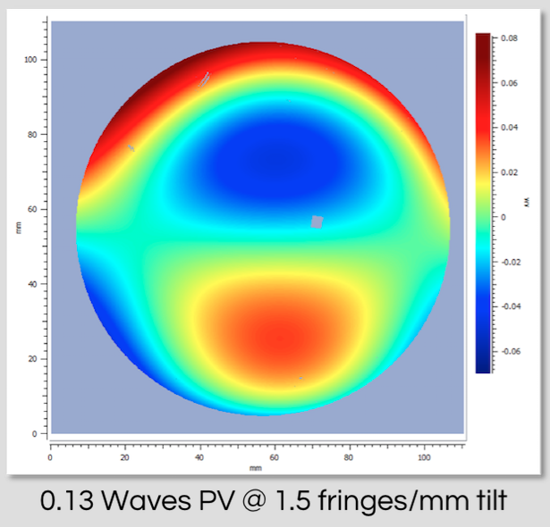
Investigation revealed the root cause of the variation. User-1 adjusted to <3 tilt fringes to near null. User-2 adjusted to 7 to 10 tilt fringes. 7 to 10 fringes was enough to introduce measureable retrace error to cause the variation and falsely failed parts.

In Classic Continuous Zoom Systems, Tilt Fringes Degrade Results

Retrace error is not controlled in zoomed imaging classical interferometers. Consequently tilt fringes degrade results. Strangely even most high-end interferometers today do not specify retrace error. Why not? Retrace error is important to everyday measurements.

Recipe for Best Results: Window Transmitted Wavefront

  • Align the transmission flat (TF), ÄPRE Application Note: How to Align a TF
  • Align the reference flat (RF) until the fringes are nulled
    • This minimizes Retrace Errors
  • Measure the cavity without the window
  • Save the resulting measurement to the Clipboard
  • Subtract Reference (Analysis Tools) with the cavity measurement selected
    • Removes TF/RF cavity residual errors
  • Place the window into the cavity
  • Tilt the window just enough so no window fringes are seen
  • Measure and report the results

Retrace Errors also Influence Spherical Surface Testing

The presence of tilt fringes in a classical zoom system will degrade any measurement, even spheres and flats. Only the ÄPRE S-Series minimizes retrace error. An ÄPRE S-Series interferometer, exhibits <λ/20 Retrace Error at 500 fringes! With the S-Series retrace error induced user to user variations are nearly nonexistent.

Spectrally Controlled Interferometry – Wins Prestigious Award

ÄPRE’s Spectrally Controlled Interferometry was awarded one of Laser Focus World’s highest awards for innovation in photonics, a Gold-Level Honoree.

We are proud to be recognized by this leading industry journal for the innovation that SCI brings to optical testing.

Even more exciting is hearing from our customers how SCI saves time and money as plates do not require painting or wedging to measure, and miniature optics are finally measurable with an interferometer!

Plus it can be added to ÄPRE’s S-Series interferometers now or in the future as they are SCI ready, or your old interferometer can be upgraded with an SCI source.

Contact us to learn more.


International Optics Participation at Eclipse 2017

Casper, WY USA, August 21, 2017
by Bob Smythe

Telescopes and amateur astronomy are hobbies for many optical professionals. Observing a total eclipse is a peak experience for any astronomer, as it dramatically gives a fleeting glimpse of the solar corona and a sense of the precision motions of the solar system.

My first and (to date) only eclipse was in July 1972 in New Brunswick, Canada, seen between thunder heads on a stormy afternoon. I swore that would not be my last. This year, after 45 years, was a chance to see another, and in clear skies of the American west. My expectations were not disappointed.

The Global Optics Community

This eclipse brought together friends and colleagues from around the world and showed me how much we have in common. The build up was enhanced through meeting with colleagues at international, OSA and SPIE conferences and tradeshows from late spring and through the summer.

OPTICS & PHOTONICS International Exhibition, Japan

Friends from Kiyohara Optical Japan

While visiting Japan I met with Motosuke Kiyohara of Kiyohara Optics, Tokyo, Japan. We immediately found common interest in astronomy (Kiyohara even has a small telescope store next to their home office!) and I learned of his intention to observe the eclipse in Casper WY, my target city too. We agreed to meet for dinner the night before the eclipse IF we could get a hotel. After much frustration we finally got a hotel room and were able to meet as planned and enjoyed a wonderful evening with our Kiyohara friends and family.

OSA Optical Fabrication and Testing

At OF&T in July I met my friend Dave Stephenson (Jenoptik Jupiter FL). We discussed the eclipse and our intentions to travel to Wyoming. The problem was hotels. On Dave’s recommendation we booked a hotel closer to centerline. Upon checking in at the Ramada Cheyenne we ran into Dave and his wife adding a very pleasant surprise! Plus the hotel was a buzz of eclipse chasers with Sky and Telescope magazine hosting seminars in the hotel.

SPIE Optics & Photonics

At SPIE Optics and Photonics Senior Member breakfast the eclipse was the center of discussion. Three table members from Ball Aerospace, Boulder CO were heading up to Wyoming to observe the eclipse. The big question was how to deal with the traffic, but the excitement was building.

During the exhibits I ran into John Hayes. John and I were competitors for years as we worked to serve the same customers with our interferometers, he at Wyko and me at Zygo®. It was a pleasure to learn of his dedication to amateur astronomy and his intentions to view the eclipse in Oregon, his home state. We learned that we grew up within 10 Km of each other in the Detroit MI area, are were part of the same astronomy club, observed at the same sites and never knew each other!

Casper WY Festivities

Viewing solar prominences the day before the eclipse

Viewing solar prominences indicated the west side of the corona would be more active due to a sun spot coming into view on the eastern solar horizon and it was.

 The Eclipse!

With near perfect skies Casper WY turned out to be a fortunate choice. The views of the corona and solar prominences were subtle and awe inspiring even through simple binoculars or simply the naked eye. This eclipse let me see how like minded the global optics community is, even previous competitors! Something to keep in mind and appreciate as we enjoy the pursuit of our careers.

KOptic group observing eclipse
Outer Corona: Photo by R. Smythe
Inner Corona. Photo by Moto Kiyohara

China International Optoelectronic Exposition (CIOE)


The China International Optoelectronic Exposition (CIOE) is the world’s largest exhibition serving the optics & photonics industry. 2017 was Äpre Instruments first occasion to actively participate and exhibit at CIOE.

Strong interest in ÄPRE’s S-Series Interferometers in China

With more than 60,000 visitors attending CIOE over the four days of the exhibition, booth traffic was heavy every day and there was tremendous interest shown in ÄPRE’s high performance S-Series interferometers, Reveal Software and our new SCI technology.

Optics professionals from the world over were in attendance at CIOE and all found it helpful, positive and refreshing to visit with APRE and learn that there is a company addressing the needs and requirements for high performance – high precision optical metrology and interferometry.

With a new Chinese distributor, Chongqing Fuma Precision Equipment Company, growing interferometer sales in China and our well-received participation at CIOE, it is safe to say Äpre Instruments is now well positioned for solid business growth in China.

Laser Munich 2017

Jan Posthumas of LaserPeak (on left) and Don Pearson, ÄPRE’s VP Sales (on right)

Don Pearson, our VP Sales and Jan Posthumas, of LaserPeak (ÄPRE Representative) presented ÄPRE’s S100|HR interferometer in Munich this June. Once again we were pleased to meet with, and make new friends while co-exhibiting with the PTB’s HLEM (Hi-Level Experts Meeting) group.

Presented was the S100|HR, part of ÄPRE’s S-Series interferometers with diffraction limited imaging to 50 µm resolution (S50|HR), and all with <0.1% image distortion and <λ/20 retrace errors even at 6.5 fringes/mm.

We were also pleased with the interest in our new SCI based system that electronically remove back reflections from measurements and we look forward to discussing this more in the future.


Photonics West 2017 Introductions

Don Pearson, VP Sales and Takuya Mikami of Okamoto Optics Works discuss ÄPRE’s S100|HR interferometer

It was great to meet many new and old friends in San Francisco at Photonics West. Tradeshows give all of us an opportunity to discuss the challenges and opportunities facing us and discovering how working together we can help each other. Photonics West was no exception.

This year we introduced the latest member of ÄPRE, Don Pearson Vice President Sales. Don comes to ÄPRE with a long history selling and applying interferometers and is known to many in the industry. Previously of Mahr and Trioptics Don is looking forward to meeting you and seeing how we can work together.

We also introduced to Photonics West our S100|HR laser Fizeau interferometer. We are pleased at its reception and how measuring mid-spatial frequencies and form with one instrument is a cost and time savings. Plus accurately measuring 5X more slopes gets the final figuring process started sooner, saving time.

Contact us to discuss how we might work together.

ÄPRE Laser Focus World Article Published

This month (November 2016) Laser Focus World published our paper “Three Simple Tests to Assess Interferometer Performance. Let us know what you think.

Also get Äpre’s test target that is required to assess the imaging performance of your interferometer.

Results of the Retrace Error Test in a Generation II Interferometer

Shown here is a Generation II interferometer (ground glass disk with continuous zoom system) that exhibits significant retrace error with tilt.


fig-3-a-apre
Generation II laser Fizeau Interferometer exhibiting significant retrace errors with only 1.5 fringes/mm tilt

Interferometer Imaging Test Target

ÄPRE is offering a free interferometer image resolution test target. The target is simple to use without requiring complicated and expensive phase stepped optics. Simply place the 1-cycle/mm test target in front of your interferometer and look at its image on your camera. If you cannot see these lines, you cannot measure surfaces to these fine of details. Also if a zoom system is present you can zoom in and see if the resolution improves, stays the same or degrades.

Send us your contact information including your email address and mail delivery address and we will mail you a target.

Test Results On Generation II Laser Fizeau Interferometer

Here is shown a Generation II interferometer (Ground Glass with Continuous Zoom Imaging System) demonstrating lost resolution at the edges of the field.

Fizeau Interferometer: Fringes? Waves? Measured? Displayed?

The basic interferometry units of Fringe and Waves can get confused. This confusion leads to out of specification parts shipping and good parts scraped. This blog addresses fringes versus waves.

Examples reference ÄPRE REVEAL software, similar controls are available in other interferometer analysis software.

Note

In this text we will use the terms “display fringes” and “measurement fringes” whereas in the drop down menu they are listed as “fringes, display” and “fringes, measurement”. The drop down menu uses this order of words to keep the listing of the two together. In this write up the more natural order of words will be used for fringes and waves.

Fringes

The native measurement unit in an interferometer is the fringe. The interferometer simply creates bright to dark bands called fringes which have to be interpreted. The analysis software (or observer) interprets the fringe measurement by knowing the wavelength of the light, the interferometer optical configuration, and for the analysis software the display units. Thus to know what a fringe means all these parameter require input.

Four height units associated with these are “fringe, measurement”, “fringe, display”, “wave, measurement”, and “waves, display”. These are accessed from the height units ICON in the ICON bar near the top of the tools shown in Figure 1.


Measurement Fringes

In REVEAL the native fringe unit is the measurement fringe. “measurement fringe” is the native measurement unit without interpretation. In other words measurement fringe is the direct measure of the optical wavefront entering the interferometer, regardless of how it got there. Most interferometer measurements require knowing how the wavefront was created, but there are measurements, like single pass optical wavefront measurements that use measurement fringes as their result.

Display Fringes

Display fringe” is used if fringes are specified at a wavelength other than the available interferometer wavelength. The function of display fringe is to display the fringes scaled to the desired wavelength.

Within REVEAL the native interferometer wavelength, “measurement wavelength” and the “display wavelength” are set in the Measurement Configuration controls under the Analysis Tools shown in Figure 2.

When the “Display Wavelength” [632.8 nm in figure 2] and “Measurement wavelength” [10,000 nm or 10 um in figure 2] differ REVEAL calculates the ratio and displays how the part WOULD measure if measured at the “display wavelength”. This simplifies analysis, assuring fewer errors during the measurement process. In figure 3 a&b measurement fringes and display fringes are shown for the settings in figure 2.

Waves

Waves add another level of scaling to the results due to interferometer test configuration. Referring to figure 2, the waves per fringe control is set as a function of the test configuration. The most common configuration is the surface test. For the surface test the waves per fringe control is set to 0.5, which is the REVEAL default value. What this means is a fringe is equal to 0.5 of a fringe. In the case of a 632.8 nm wavelength interferometer a wave is equal to 316.4 nm. In reflection all surface deviations have the wavefront pass them twice, or 2-pass as shown in figure 4. An example of a 4-pass setup, where the waves per fringe is 0.25 is the autocollimating parabola mirror test as shown in figure 5.


Measurement Wavelength

Wavelength, measurement (mwv) is scaled by the interferometer setup and displayed in the native interferometer measurement wavelength. The measurement wavelength and the result wavelength are the same. This is analogous to fringe, measurement being scaled by the setup driven waves per fringe. Results for the settings in Figure 2 are displayed in figure 6a.

Display Wavelength

Display Wavelength (wv) is analogous to fringe, display were the result is scaled to the desired specification wavelength. Wavelength, display scales the fringe, measured by the waves per fringe and the display wavelength.